STARPOINT Lifting Eye - WLL in metric tonnes, bolted and adjusted to the direction of pull
Type
TON
M8
-
1
0.4
2
0.8
0.56
0.4
0.4
0.84
0.6
0.4
M10
3/8"-16UNC
1
0.4
2
0.8
0.56
0.4
0.4
0.84
0.6
0.4
M12
1/2"-13UNC
2
0.75
4
1.5
1
0.75
0.75
1.6
1.12
0.75
M16
5/8"-11UNC
4
1.5
8
3
2.1
1.5
1.5
3.15
2.25
1.5
M20
3/4"-10UNC
6
2.3
12
4.6
3.22
2.3
2.3
4.83
3.45
2.3
-
7/8"-9UNC
6
2.3
12
4.6
3.22
2.3
2.3
4.83
3.45
2.3
M24
1"-8UNC
8
3.2
16
6.4
4.48
3.2
3.2
6.7
4.8
3.2
M30
1 1/4"-7UNC
12
4.5
24
9
6.3
4.5
4.5
9.4
6.7
4.5
M36
1 1/2"-6UNC
16
7
32
14
9.8
7
7
14.7
10.5
7
M42
1 3/4"-5UNC
24
9
48
18
12.6
9
9
18.9
13.5
9
M48
2"-4.5UNC
32
12
64
24
16.8
12
12
25.2
18.0
12
Inchs Measurements
Method of lift
Number of legs
1
1
2
2
2
2
2
3 and 4
3 and 4
3 and 4
Angle < ЉЌ
0ЁЦ
90ЁЦ
0ЁЦ
90ЁЦ
0-45ЁЦ
45-60ЁЦ
КёДыФЊ
0-45ЁЦ
45-60ЁЦ
КёДыФЊ
Factor
-
1
-
2
1.4
1
1
2.1
1.5
1
Metric
inchs
STARPOINT Lifting Eye - WLL in Pounds (lb), bolted and adjusted to the direction of pull
Type
LBS
M8~10
3/8" -16UNC
2200
880
4400
1760
1235
880
880
1850
1320
880
M12
1/2" -13UNC
4400
1650
8800
3300
2200
1650
1650
3460
2470
1650
M16
5/8" -11UNC
8820
3300
17640
6610
4630
3300
3300
6940
4960
3300
M20
3/4" -10UNC
13250
5070
26500
10140
7100
5070
5070
10650
7600
5070
-
7/8" -9UNC
13250
5070
26500
10140
7100
5070
5070
10650
7600
5070
M24
1" -8UNC
17630
7050
35260
14100
9880
7050
7050
14800
10580
7050
M30
1 1/4" -7UNC
26450
9920
52900
19840
13880
9920
9920
20800
14880
9920
M36
1 1/2"-6UNC
35270
15430
70540
30860
21600
15430
15430
32400
23150
15430
M42
1 3/4" -5UNC
52900
19480
105800
39680
27700
19840
19840
41600
29760
19840
M48
2" -4.5UNC
70550
26450
141100
52910
37000
26450
26450
55500
39680
26450
Ёп User Instructions
1. Reference should be made to German Standards accord. BGR 500 or other country specific statutory regulations and inspections are to be carried out by competent persons only.
2. Before installation and every use, inspect visually RUD lifting points, paying particular attention to any evidence of corrosion, wear, weld cracks and deformations. Please ensure compatibility of bolt thread and tapped hole.
3. The material construction to which the lifting point will be attached should be of adequate strength to withstand forces during lifting without deformation. For steel S235JR (1.0037) or Cast iron GG 25 (0.6025 - without blowhole) the bolt length should be 1.5xM (=L). When lifting light metals, nonferrous metals and gray cast iron or other materials the thread has to be chosen in such a way that the WLL of the thread corresponds to the requirements of the corresponding base material.
The German testing authoritiy, BG, recommends the following minimum for the bolt lengths:2 x M in aluminium 2.5 x M in aluminium-magnesium alloys (M = thread ЈЊ, e.g. M 20)
4. The lifting points must be positioned to the load in such a way that movements are avoided during lifting. a.) For single leg lifts, the lifting point should be vertically above the centre of gravity of the load. b.) For two leg lifts, the lifting points must be equidistant to/or above the centre of gravity of the load. c.) For three and four leg lifts, the lifting points should be arranged symmetrical around the centre of gravity, in the same plane if possible.
5. Load symmetry: The required WLL of the individual RUD lifting point are calculated using the following formula and are based on symmetrical loading:
W.L.L =
W n x cos ЉЌ
W.L.L = Working Load Limit W = Load Weight (kg) n = Number of load bearing legs ЉЌ = Angle of inclination of the chain to the vertical
The calculation of load bearing legs is as follows:
No. Legs
Symmectry(ДыФЊ)
Asymmetry (КёДыФЊ)
Two Leg
2
1
Three / Four Leg
3
2
6. Planar bolting surface (E) must be guaranteed. Countersink of thread hole = nominal thread diameter. The holes must be drilled with sufficient depth in order to guarantee compatibility with the supporting surface.
7. For fitting without tools and for inspection of the compatibility of bolt thread and tapped hole, the STARPOINT can be delivered with a tempered key (type: VRS-F). Engage key into hexagon socket screw - fitting and removal is possible by hand - then disengage key. In case of fitting with key, tighten by hand. Do not use an elongation piece. For a long term application the VRS should be tightened with torque according table 1 (+/- 10%).
8. Shock loading or vibrations can cause unintentional dismantling. To protect against this: liquid thread locker such as Loctite (depending on the application, please pay attention to the manufacturer's instruction). Attention: Ring Body has to be free to rotate.
9. The STARPOINT has to be adjustable through 360ЁЦ when fitted and with key disengaged . Adjust to direction of pull before attaching of the lifting means. Attention: STARPOINT's are not suited for turning under load
10. All fittings connected to the STARPOINT should be free moving. When connecting and disconnecting the lifting means (sling chain) pinches and impacts should be avoided. Damage of the lifting means caused by sharp edges should be avoided as well. For lifting points which remains on the construction we basically recommend to secure with liquid locking device and tighten with torque.
11. Effects of temperature: Due to the DIN/EN bolts that are used with the STARPOINT the working load limit should be reduced accordingly: -40ЁЦ to 100ЁЦC = no reduction 100ЁЦ to 200ЁЦC = minus 15% 200ЁЦ to 250ЁЦC = minus 20% 250ЁЦ to 350ЁЦC = minus 25% Temperatures above 350ЁЦC are not permitted.
12. RUD lifting points must not be used under chemical influences such as acids, alkaline solutions and vapours e.g. in pickling baths or hot dip galvanising plants. If this cannot be avoided, please contact the manufacturer indicating the concentration, period of penetration and temperature of use.
13. The position where the lifting points should be attached should be clearly marked with colour.
14. After fitting, an annual inspection, or sooner if conditions dictate, should be undertaken by a competent person examining the continued suitability. Also after damage and special occurrences.
Inspection criteria concerning paragraphs 2 and 14:
Ensure compatibility of bolt thread and tapped hole.
The lifting point should be complete.
The working load limit and manufacturers stamp should be clearly visible.
Deformation of the component parts such as body and bolt.
Mechanical damage, such as notches, particularly in high stress areas.
Wear should be no more than 10% of cross sectional diameter.
Evidence of corrosion.
Evidence of cracks.
Damage to the bolt and/or thread.
The body of the STARPOINT must be free to rotate.
Ёп Description
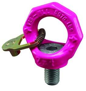
Starpoint Vario Eyebolts - RUD VRS (Will swivel to direction of the load).
VRS
VRS-F
The VRSStandard does not include the locking device (StarKey) which makes the eyebolt adjustable. The VRS-F Can be fixed in position or made adjustable by dis-engaging the StarKey (locking device).
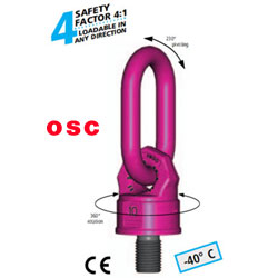
Eyebolt Information Star shaped design, a clear distinction from the DIN 580 eye bolt. With a striking fluorescent pink powder coating.
Identification: Clear WLL indication for the most unfavorable load direction F (not permissible for DIN 580). Forged material (1.6541) alloy quenched and tempered, high tensile and annealed, Body and bolt, 100% electromagnetic alloy crack tested in accordance with specification EN 1677-1 and Design factor of 4:1 in any direction.
Choose the attachment point in such a way that the introduced forces are accomodated by the work piece without being deformed. Make sure the bolting surface is plain. Ensure an appropriate bore depth to facilitate an optimal sitting of the engaging surface. Work piece material, at least 1.0037 (St 37).
For light metals, nonferrous heavy metals and grey cast iron, the thread type allocation must be done in such a way that, the WLL of the thread type fulfills the requirements of the respective work piece.
Without an additional washer, screw the VRS into the work piece until the seat - engaging surface of the Hexagon socket bolt evenly lies on the surface of the work piece. If the VRS is to permanently remain at the point of force introduction, it must be tightened with a torque of 10 Nm.
The thread bore countersink is equal to the effective diameter of the thread. Always pay attention that the Hexagon socket bolt is tightened.
When impact loaded or operated in environments with skewing and vibrations, unintentional loosening can happen, especially if through bolts with nuts are used.
Securing possibilities: Use of a liquid thread securing medium eg. Loctite ( follow the manufacturer`s recomendations) In a tightened condition, the VRS must be able to swivel up to 360ЁЦ. Before loading, adjust the VRS to the direction of the applied force. A captive Hexagon socket bolt.
The VRS is patent protected : GM 9402014 - and further industrial property rights are registered under GM 9316475. For the toolless assembling, the STARPOINT is supplied with an annealed star - profile - key.
Simply engage the Hexagon socket bolt with the star - profile - key and use your fingers to respectively tighten or untighten the arrangement . Disengage the key. The VRS is rotatable!
Eye bolt VRS in pink - can be adjusted to the direction of pull. Higher load capacities than DIN 580-Eyebolts.
Attention: Lateral loads with eye bolts acc. to DIN 580 are forbidden. With multiple-point-suspensions at 2- leg and 3 / 4-leg, the positioning of the eye bolt has to be in the direction of pull. This can only be realized with RUD STARPOINT eye bolts as they are adjustable to the direction of pull when fitted.
Proof Testing There is no requirement to Proof Test RUD Products, either Bolt or Weldable after Installation if the user instructions for welding are carried out correctly. The welding should be carried out by a suitably qualified and competent welder/person.
The supporting structure, or the load, should be of adequate strength to take the stresses involved and this is the responsibility of the engineering designer or equivalent.
RUD Lifting and Lashing Products are Manufactured and conform to EN 1677. No further Proof Testing in the field is required. In fact it would be considered that the Product had been overloaded if a Load more than the recommended Working Load Limit had been applied.
RUD products should be regularly inspected in line with the requirements of LOLER and as per our user instructions at intervals decided by a competent person.
ЂР Renference : RUD, LiftingSafety ЂР Please feel free to call: 02-896-5656 or Fax: 02-896-5659 or contact us via e-mail(8965656@hanmail.net) so our company can help you obtain the correct equipment for your applications.


 1ШЃРЬНКЦЎИЕ-ДмСЖ ЛѓММКИБт