|
|
 |
|
 |
|
8호이스트...
|
|
|
 |
|
1호이스트...
|
|
|
 |
|
1호이스트...
|
|
|
 |
|
1호이스트...
|
|
|
 |
|
1호이스트...
|
|
|
 |
|
1호이스트...
|
|
|
 |
|
7아이볼트
|
|
|
 |
|
1호이스트...
|
|
|
|
 |
1호이스트링
|
|
|
|
♣1. Ultimate Load is 5 times the Working Load Limit
♣2. Individually proof loaded to 2.5 times the Working Load Limit
based on the 5 :1 design factor.
♣3. Material : Alloy components are alloy steel
♣4.Fatigue tested to 300% rated load over 5,000 times of continual pulling and releasing.
♣5. Finish : Black oxide on surface for corrosion resistance.
♣6. Range of Movement : 360° swivel and 180° plvot action.
♣7. Heat treatment : Quenched & Temperd
♣8.100% individually proof tested to 2.5 times the Working Load Limit with certification and Statistically Magnetic Particle inspected.(Clevis, Base, Clevis Pins, Washer and Bushing)
♣9. Bolt specification is a Grade 12.9 Alloy socket head screw to DIN 912.
♣10. All threads are metric (ASME/ANSI B 18.3.1m)
♣11.Special Order : Also available in Nickel and Stainless Steel
(600 grades).
♣12. RoHS(Restriction of Hazardous Substances Directive
it restricts the use of the following six substances:
Pb, Hg, Cd, Cr6+, PBB, PBDE)
-(2006년 유럽 유해물질 제한지침에 의거 무전해 도금한
친환경적인 제품) |
♣13. 공식 사용처-Samsung, LG, Hyundai, STX, Daewoo, Posco,
유니슨, KHNP, Avaco, iones, | |
|
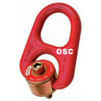
Center Pull Hoist Ring |
|
item
No. |
W.L.L
(ton) |
Thread
Size |
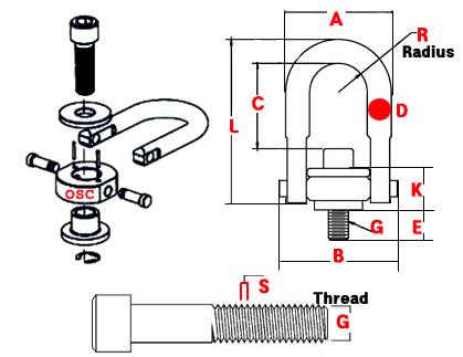
Dimensions(mm) |
Torque
kg/m |
Weight
kg |
|
G |
S |
E |
A |
D |
B |
C |
L |
K |
R |
|
HFM000 |
0.4 |
M8 |
1.25 |
7 |
40.5 |
9.53 |
48.5 |
31 |
66.7 |
22.5 |
11.5 |
1.0 |
0.17 |
|
HFM001 |
0.4 |
M8 |
1.25 |
15.8 |
40.5 |
9.53 |
48.5 |
31 |
66.7 |
22.5 |
11.5 |
1.0 |
0.17 |
|
HFM002 |
0.5 |
M10 |
1.5 |
15.8 |
40.5 |
9.53 |
48.5 |
29 |
66.7 |
22.5 |
11.5 |
1.5 |
0.17 |
|
HFM020 |
1.05 |
M12 |
1.75 |
23.3 |
82.6 |
19.05 |
89.5 |
65 |
120.65 |
34.6 |
22.23 |
3.7 |
1.08 |
|
HFM120 |
1.05 |
M12 |
1.75 |
23.3 |
82.6 |
19.05 |
89.5 |
114 |
170.18 |
34.6 |
22.23 |
3.7 |
1.28 |
|
HFM021 |
1.05 |
M12 |
1.75 |
28.3 |
82.6 |
19.05 |
89.5 |
65 |
120.65 |
34.6 |
22.23 |
3.7 |
1.09 |
|
HFM121 |
1.05 |
M12 |
1.75 |
28.3 |
82.6 |
19.05 |
89.5 |
114 |
170.18 |
34.6 |
22.23 |
3.7 |
1.29 |
|
HFM022 |
1.9 |
M16 |
2.0 |
23.3 |
82.6 |
19.05 |
89.5 |
58 |
120.65 |
34.6 |
22.23 |
8.4 |
1.12 |
|
HFM122 |
1.9 |
M16 |
2.0 |
23.3 |
82.6 |
19.05 |
89.5 |
107 |
170.18 |
34.6 |
22.23 |
8.4 |
1.32 |
|
HFM023 |
1.9 |
M16 |
2.0 |
28.3 |
82.6 |
19.05 |
89.5 |
58 |
120.65 |
34.6 |
22.23 |
8.4 |
1.13 |
|
HFM123 |
1.9 |
M16 |
2.0 |
28.3 |
82.6 |
19.05 |
89.5 |
107 |
170.18 |
34.6 |
22.23 |
8.4 |
1.33 |
|
HFM024 |
1.9 |
M16 |
2.0 |
33.3 |
82.6 |
19.05 |
89.5 |
58 |
120.65 |
34.6 |
22.23 |
8.4 |
1.14 |
|
HFM124 |
1.9 |
M16 |
2.0 |
33.3 |
82.6 |
19.05 |
89.5 |
107 |
170.18 |
34.6 |
22.23 |
8.4 |
1.34 |
|
HFM025 |
2.15 |
M20 |
2.5 |
33.3 |
82.6 |
19.05 |
89.5 |
54 |
120.65 |
34.6 |
22.23 |
14 |
1.19 |
|
HFM125 |
2.15 |
M20 |
2.5 |
33.3 |
82.6 |
19.05 |
89.5 |
103 |
170.18 |
34.6 |
22.23 |
14 |
1.39 |
|
HFM026 |
2.15 |
M20 |
2.5 |
38.3 |
82.6 |
19.05 |
89.5 |
54 |
120.65 |
34.6 |
22.23 |
14 |
1.2 |
|
HFM126 |
2.15 |
M20 |
2.5 |
38.3 |
82.6 |
19.05 |
89.5 |
103 |
170.18 |
34.6 |
22.23 |
14 |
1.4 |
|
HFM040 |
3 |
M20 |
2.5 |
35.8 |
122.2 |
25.4 |
132.4 |
90 |
165.1 |
46.5 |
35.72 |
14 |
3.03 |
|
HFM140 |
3 |
M20 |
2.5 |
35.8 |
122.2 |
25.4 |
132.4 |
130 |
205.74 |
46.5 |
35.72 |
14 |
3.35 |
|
HFM041 |
3 |
M20 |
2.5 |
40.8 |
122.2 |
25.4 |
132.4 |
90 |
165.1 |
46.5 |
35.72 |
14 |
3.03 |
|
HFM141 |
3 |
M20 |
2.5 |
40.8 |
122.2 |
25.4 |
132.4 |
130 |
205.74 |
46.5 |
35.72 |
14 |
3.35 |
|
HFM042 |
4.2 |
M24 |
3.0 |
30.8 |
122.2 |
25.4 |
132.4 |
86 |
165.1 |
46.5 |
35.72 |
31 |
3.1 |
|
HFM142 |
4.2 |
M24 |
3.0 |
30.8 |
122.2 |
25.4 |
132.4 |
130 |
205.74 |
46.5 |
35.72 |
31 |
3.42 |
|
HFM043 |
4.2 |
M24 |
3.0 |
36 |
122.2 |
25.4 |
132.4 |
86 |
165.1 |
46.5 |
35.72 |
31 |
3.12 |
|
HFM143 |
4.2 |
M24 |
3.0 |
36 |
122.2 |
25.4 |
132.4 |
130 |
205.74 |
46.5 |
35.72 |
31 |
3.44 |
|
HFM060 |
7 |
M30 |
3.5 |
46 |
152.4 |
31.75 |
166.7 |
114 |
222.25 |
63.2 |
44.45 |
60 |
6.3 |
|
HFM061 |
11 |
M36 |
4.0 |
70 |
203.2 |
44.45 |
215.7 |
164 |
316.7 |
72.6 |
57.15 |
100 |
15.5 |
|
HFM062 |
12.5 |
M42 |
4.5 |
80 |
203.2 |
44.45 |
215.7 |
158 |
316.7 |
72.6 |
57.15 |
100 |
16 |
|
HFM063 |
13.5 |
M48 |
5.0 |
80 |
203.2 |
44.45 |
215.7 |
152 |
316.7 |
72.6 |
57.15 |
100 |
16.8 |
|
HFM080 |
22 |
M64 |
6.0 |
98 |
266 |
57 |
296 |
213 |
400 |
104 |
76 |
290 |
40 |
|
HFM081 |
30 |
M72 |
6.0 |
118 |
330 |
70 |
336 |
239 |
470 |
139 |
95 |
594 |
75 |
|
HFM082 |
51 |
M90 |
6.0 |
177 |
370 |
83 |
404 |
|
561 |
153.3 |
102 |
663 |
120.2 | |
|
INCH Specification |
|
item
No. |
Thread
Size |
W,L,L
Lbs |
Dimension (inch) |
Torque
ft / Lbs |
Weight
Lbs |
|
A |
E |
L |
R |
|
HFU600 |
5/16-18 |
800 |
1.59 |
0.28 |
2.63 |
0.45 |
7 |
0.3 |
|
HFU601 |
5/16-18 |
800 |
1.59 |
0.28 |
2.63 |
0.45 |
7 |
0.3 |
|
HFU602 |
3/8-16 |
1,000 |
1.59 |
0.49 |
2.63 |
0.45 |
12 |
0.3 |
|
HFU620 |
1/2-13 |
2,500 |
3.25 |
0.75 |
4.75 |
0.88 |
28 |
2.6 |
|
HFU720 |
1/2-13 |
2,500 |
3.25 |
0.75 |
6.7 |
0.88 |
28 |
3.04 |
|
HFU621 |
1/2-13 |
2,500 |
3.25 |
0.97 |
4.75 |
0.88 |
28 |
2.6 |
|
HFU721 |
1/2-13 |
2,500 |
3.25 |
0.97 |
6.7 |
0.88 |
28 |
3.04 |
|
HFU622 |
5/8-11 |
4,000 |
3.25 |
0.75 |
4.75 |
0.88 |
60 |
2.6 |
|
HFU722 |
5/8-11 |
4,000 |
3.25 |
0.75 |
6.7 |
0.88 |
60 |
3.04 |
|
HFU623 |
5/8-11 |
4,000 |
3.25 |
0.97 |
4.75 |
0.88 |
60 |
2.6 |
|
HFU723 |
5/8-11 |
4,000 |
3.25 |
0.97 |
6.7 |
0.88 |
60 |
3.04 |
|
HFU624 |
5/8-11 |
4,000 |
3.25 |
1.25 |
4.75 |
0.88 |
60 |
2.6 |
|
HFU724 |
5/8-11 |
4,000 |
3.25 |
1.25 |
6.7 |
0.88 |
60 |
3.04 |
|
HFU625 |
3/4-10 |
5,000 |
3.25 |
1.25 |
4.75 |
0.88 |
100 |
3.0 |
|
HFU725 |
3/4-10 |
5,000 |
3.25 |
1.25 |
6.7 |
0.88 |
100 |
3.44 |
|
HFU626 |
3/4-10 |
5,000 |
3.25 |
1.5 |
4.75 |
0.88 |
100 |
3.0 |
|
HFU726 |
3/4-10 |
5,000 |
3.25 |
1.5 |
6.7 |
0.88 |
100 |
3.44 |
|
HFU640 |
3/4-10 |
7,000 |
4.81 |
1.26 |
6.5 |
1.41 |
100 |
7.0 |
|
HFU740 |
3/4-10 |
7,000 |
4.81 |
1.26 |
8.1 |
1.41 |
100 |
7.72 |
|
HFU641 |
3/4-10 |
7,000 |
4.81 |
1.51 |
6.5 |
1.41 |
100 |
7.0 |
|
HFU741 |
3/4-10 |
7,000 |
4.81 |
1.51 |
8.1 |
1.41 |
100 |
7.72 |
|
HFU642 |
7/8-9 |
8,000 |
4.81 |
1.26 |
6.5 |
1.41 |
160 |
7.0 |
|
HFU742 |
7/8-9 |
8,000 |
4.81 |
1.26 |
8.1 |
1.41 |
160 |
7.72 |
|
HFU643 |
7/8-9 |
8,000 |
4.81 |
1.51 |
6.5 |
1.41 |
160 |
7.0 |
|
HFU743 |
7/8-9 |
8,000 |
4.81 |
1.51 |
8.1 |
1.41 |
160 |
7.72 |
|
HFU644 |
1 - 8 |
10,000 |
4.81 |
1.26 |
6.5 |
1.41 |
230 |
7.5 |
|
HFU744 |
1 - 8 |
10,000 |
4.81 |
1.26 |
8.1 |
1.41 |
230 |
8.22 |
|
HFU645 |
1 - 8 |
10,000 |
4.81 |
1.5 |
6.5 |
1.41 |
230 |
7.6 |
|
HFU745 |
1 - 8 |
10,000 |
4.81 |
1.5 |
8.1 |
1.41 |
230 |
8.32 |
|
HFU660 |
1 1/4-7 |
15,000 |
6 |
1.77 |
8.75 |
1.75 |
470 |
14 |
|
HFU661 |
1 1/2-6 |
24,000 |
8 |
2.74 |
12.47 |
2.25 |
800 |
34 |
|
HFU662 |
2 -4 1/2 |
30,000 |
8 |
3.24 |
12.47 |
2.25 |
800 |
36 |
|
HFU680 |
2 1/2-4 |
50,000 |
10.5 |
3.98 |
16.88 |
3.0 |
2100 |
88 |
|
HFU681 |
3-4 |
75,000 |
13 |
5.3 |
19.5 |
3.75 |
4300 |
166 |
|
HFU682 |
3 1/2-4 |
100,000 |
14.58 |
7 |
22.09 |
4.0 |
6600 |
265 |
|
300% rated load tensile fatigue test (삼성중공업 제출) |
 |
|
The above graph is about 300% rated load tensile fatigue test of HFM063 (13.5 ton) safety engineered hoist ring.
As you can see in the graph, tensile strengh test was done based on 300% (3 times) rated load.
(♣3배의 하중으로 연속 5,000회 이상 인장피로도 검사를 실시하여 품질기준을 통과한 제품)
*Rated Load of HFM063 is 13.5 ton
*Tensile test given on over 39.91 ton(about 300% over rated load given to HFM063).
*Test date: December 5th, 2011.
*Cycles of fatigue test: 2,500 cycles.
*Cycles of fatigue test until broke: 6,302 cycles.
We guarantee safety Engineered Hoist Rings go over 20,000 cycles with 150% rated load (1.5 times than given rated load).
However never eve exceed rated load given to each hoist rings.
The safety factor is just in cases of mis-use or unexpected and uncontrollable accidents.
We will not be responsible for accidents or risks caused by mis-use or over-use of hoist rings beyong rated load given. |
|
사용방법 |
|

| |
| |
|

|
|
Hoist Ring SAFETY INSTRUCTIONS |
|
CAUTION: Prior to using any hoist ring, Please read the following for proper insstallation and usage. As with all mechanical devices, regular inspection for wear and strict adherence to use instruction is necessary to prevent misuse failure.
♣1. Despite the 5:1 safety factor, NEVER EXCEED THE RATED LOAD CAPACITY.
This safety margin is needed in case of misuse, which could drastically lower load capacity.
♣2. Tighten mounting screws to recommended torque.
Periodically check torque because screws could loosen with extended service.
♣3 Tensile strength of parent material should be above 80,000 PSI to achieve full load rating.
For weaker material, consider through-hole mounting with a nut and washer on the other side.
♣4. AVOID SHOCK LOADING. Always lift gradually. Repeat magnetic particle inspection if shock loading ever occurs.
♣5. After installation, always check that ring rotates and pivots freely in all directions.
IMPORTANT!
♣1. The force on each hoist ring is not just the total weight divided by the number of hoist rings.
The force will be greater at lower lift angles. Make sure load is evenly distributed.
♣2. Never exceed the rated load capacity of the hoist ring.
♣3. Do not allow hoist rings to bind. If necessary use a spreader bar to avoid binding.
♣4. Spacers should not be used between the hoist ring and the mounting surface.
♣5. Mounting surface must be flat and smooth for full contact with the safety hoist ring.
Tapped mounting holes must be perpendicular to the mounting surface.
♣6. Mounting screws should be tightened to the recommended torque.
Torque should be checked periodically as bolts could loosen in extended service.
♣7. Never lift with any device, such as hooks, chains or cables that could spread or damage the bail.
♣8. Never apply shock loads and use good lifting practices.
Always lift gradually. If shock loading ever occurs, the safety lifting device should be magnetic particle inspected.
♣9. After installation, always check that ring rotates and pivots freely in all directions. |
|
Safe |
Unsafe |
|

|

|
|

|

|
|

|

|
|
♣ After slings have been properly attached to the hoist ring, apply force slowly.
♣ Make sure the bail is parallel to the direction of the load.
♣ Watch the load and be prepared to stop applying force if the load starts buckling.
♣ Buckling may occur if the load is not stiff enough to resist the compressive forces which result from the angular loading. |
♣ Slings should not be reeved from one bail to another.
♣ Do not reeve slings from one bail to another.
♣ This will alter the load and angle of loading on the hoist ring. |
 | |
|
HOIST RING APPLICATION ASSEMBLY SAFETY |
|
♣1. Use swivel hoist ring only with a ferrous metal (steel, iron) or soft metal (i.e., aluminum) loads (work piece).
Do not leave threadedend of hoist ring in aluminum loads for long time periods due to corrosion.
♣2. After determining the loads on each hoist ring, select the proper size hoist ring using
the Working Load Limit ratings in Table for Metric threads.
♣3. Drill and tap the work piece to the correct size to a minimum depth of one-half the threaded shank diameter plus
the threaded shanklength.
See rated load limit and bolt torque requirements imprinted on top of the swivel trunnion.
♣4. Install hoist ring to recommended torque with a torque wrench making sure the bushing flange meets
the load (work piece) surface.
♣5. Never use spacers between bushing flange and mounting surface.
♣6. Always select proper load rated lifting device for use with Swivel Hoist Ring.
♣7. Attach lifting device ensuring free fit to hoist ring bail (lifting ring).
♣8. Apply partial load and check proper rotation and alignment.
There should be no interference between load (work piece) and hoistring bail . |
|
HOIST RING INSPECTION/ MAINTENANCE |
|
♣1. Always inspect hoist ring before use.
♣2. Regularly inspect hoist ring parts.
♣3. Never use hoist ring that shows signs of corrosion, wear or damage.
♣4. Never use hoist ring if bail is bent or elongated.
♣5. Always be sure threads on shank and receiving holes are clean, not damaged, and fit properly.
♣6. Always check with torque wrench before using an already installed hoist ring.
♣7. Always make sure there are no spacers (washers) used between bushing flange and the mounting surface.
Remove any spacers(washers) and retorque before use.
♣8. Always ensure free movement of bail.The bail should pivot 180°and swivel 360°.
♣9. Always be sure total work piece surface is in contact with hoist ring bushing mating surface.
Drilled and tapped hole must be 90°to load (work piece) surface. |
|
OPERATING SAFETY |
|
♣1. Never exceed the capacity of the swivel hoist ring, see Table for Metric threads.
♣2. When using liftingslings of two or more legs, make sure the forces in the legs are calculated using the angle from
the vertical to the leg and selectthe proper size swivel hoist ring to allow for the angular forces.
(Note:Sling angles will de-rate sling members [chain, rope, or web-bing] but will not de-rate swivel hoist ring capacity.) |
|
WARNING |
|
♣ Loads may slip or fall if proper eye bolt assembly and lifting procedures are not used.
♣ A falling load can seriously injury or kill.
♣ Read and understand and follow instructions, diagrams and chart information before using swivel hoist ring assembly. |
♣ Please feel free to call: 02-896-5656 or Fax: 02-896-5659 or contact us via e-mail(8965656@hanmail.net)
so our company can help you obtain the correct equipment for your applications. |
| |
| |
|
 |
|
|
|
|


 1호이스트링 상세보기