|
|
 |
|
 |
|
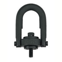
1호이스트...
|
|
|
 |
|
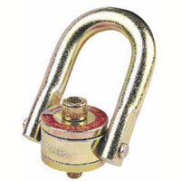
1호이스트...
|
|
|
 |
|
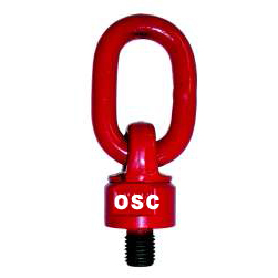
1호이스트...
|
|
|
 |
|
1호이스트...
|
|
|
 |
|
8호이스트...
|
|
|
 |
|
1호이스트...
|
|
|
 |
|
1호이스트...
|
|
|
 |
|
1호이스트...
|
|
|
|
 |
1호이스트링-가네보
|
|
 |
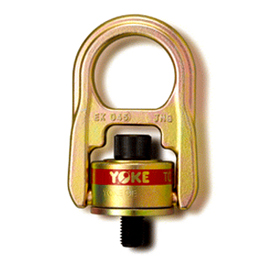
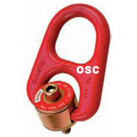
◆ Rotating Lifting Point, Grade 10
◆ The patented new design of the RLP makes it suitable also in applications where a conventional Lifting point would not be fully adequate.
Intended to be used as a Lifting point, Lashing point or Towing attachment.
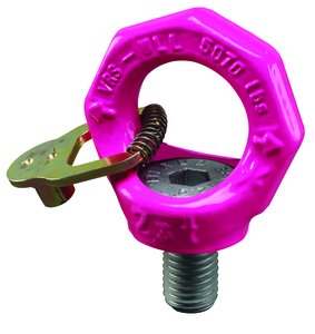
♣ Dismountable open D-ring. Enables assembly of roundsling, master link, link or hook directly onto the RLP.
♣ Hexagon-headed screw for easy assembly/disassembly by means of an ordinary wrench.
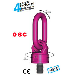
♣ RLP can rotate 360° and articulate 180°.
♣ Forged in Grade 10 material permits higher WLL than Grade 8 and DIN 580 eyebolts. |
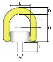
| ◆ Rotating Lifting Point (RLP) - Hoistring |
|
item
No. |
Thread
Size |
W.L.L
ton* |
Dinmesions (mm) |
Weight
kg |
|
L |
M |
B |
D |
G |
H |
|
RLP108 |
M8-10† |
0,3 |
15 |
M8 |
42 |
12 |
35 |
60 |
0,3 |
|
RLP110 |
M10-10† |
0.5 |
20 |
M10 |
42 |
12 |
34 |
60 |
0,3 |
|
RLP112 |
M12-10† |
0.75 |
19 |
M12 |
57 |
19 |
46 |
85 |
0,9 |
|
RLP116 |
M16-10† |
1.5 |
24 |
M16 |
57 |
19 |
44 |
85 |
0,9 |
|
RLP120 |
M20-10† |
2.5 |
32 |
M20 |
83 |
28 |
56 |
111 |
2,8 |
|
RLP124 |
M24-10 |
3.5 |
37 |
M24 |
83 |
28 |
53 |
111 |
2,8 |
|
RLP130 |
M30-10 |
6.0 |
49 |
M30 |
114 |
34 |
69 |
144 |
7,0 |
|
RLP136 |
M36-10 |
8.0 |
61 |
M36 |
114 |
34 |
65 |
144 |
7,3 |
|
RLP142 |
M42-10 |
14 |
65 |
M42 |
149 |
40 |
90 |
185 |
14,0 |
|
RLP148 |
M48-10 |
16 |
75 |
M48 |
149 |
40 |
86 |
185 |
14,9 |
|
♣ *Safety factor 4:1
♣†Available in UNC thread; 5/16”, 3/8”, 7/16”, 5/8”, 3/4”. |
| ◆Working Load Limits (ton) |
|
. |

|

|

|

|

|

|
|
No. of legs |
1 |
1 |
2 |
2 |
2 symmetric |
3 and 4 symmetric |
|
Load
Factor |
0°
*) |
90°
1 |
0°
*) |
90°
2 |
0-45°
1.4 |
45-60°
1 |
0-45°
2.1 |
45-60°
1.5 |
|
M8-10† |
0.67 |
0.34 |
1.35 |
0.75 |
0.47 |
0.38 |
0.7 |
0.5 |
|
M10-10† |
1.12 |
0.56 |
2.24 |
1.12 |
0.78 |
0.56 |
1.18 |
0.84 |
|
M12-10† |
1.68 |
0.84 |
3.36 |
1.68 |
1.12 |
0.84 |
1.8 |
1.27 |
|
M16-10† |
3.36 |
1.68 |
6.72 |
3.36 |
2.35 |
1.68 |
3.53 |
2.52 |
|
M20-10† |
5.6 |
2.8 |
11.2 |
5.6 |
3.92 |
2.8 |
5.88 |
4.2 |
|
M24-10 |
7.84 |
3.92 |
15.68 |
7.84 |
5.5 |
3.92 |
8.23 |
5.88 |
|
M30-10 |
13.44 |
6.72 |
26.88 |
13.44 |
9.4 |
6.72 |
14.1 |
10 |
|
M36-10 |
15.68 |
8.96 |
31.36 |
17.92 |
12.5 |
8.96 |
18.8 |
13.44 |
|
M42-10 |
17.92 |
15.68 |
35.84 |
31.36 |
22 |
15.68 |
32.93 |
23.52 |
|
M48-10 |
22.4 |
17.92 |
44.8 |
35.84 |
25.1 |
17.92 |
37.63 |
26.88 |
|
*) Provided only axial loading takes place, i.e. no bending force applied in the direction of the thread. |
|
 |
|
|
|
|


 1호이스트링-가네보 상세보기