|
|
 |
|
 |
|
1호이스트...
|
|
|
 |
|
1호이스트...
|
|
|
 |
|
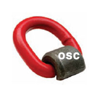
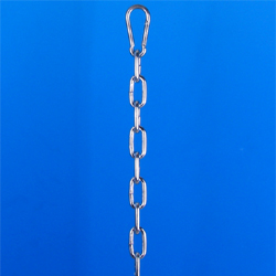
1용접링-EU
|
|
|
 |
|
1호이스트...
|
|
|
 |
|
1호이스트...
|
|
|
 |
|
1호이스트...
|
|
|
 |
|
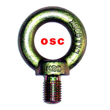
7아이볼트
|
|
|
|
 |
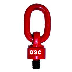
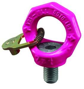
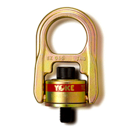
1호이스트링-varioVWBG-V
|
|
|
|
Lifting Point-Vario VWBG-V |
|
|
|
Item No |
Thread |
W.L.L |
F |
A |
B |
T |
C |
D |
E |
G |
Weigth |
Serial |
|
Size (M) |
Ton |
mm |
kg |
No. |
|
WBG100 |
M8 |
0.3 (0.4) |
13 |
8 |
31 |
76 |
29 |
30 |
28 |
36 |
0.18 |
7103720 |
|
WBG101 |
M8 |
0.3 (0.4) |
102 |
8 |
31 |
76 |
29 |
30 |
28 |
36 |
0.29 |
8600330 |
|
WBG102 |
M8 * |
0.3 (0.4) |
8-102 |
8 |
31 |
76 |
29 |
30 |
28 |
36 |
|
8600330 |
|
WBG103 |
M10 |
0.45(0.6) |
17 |
8 |
31 |
78 |
29 |
36 |
30 |
38 |
0.29 |
7103715 |
|
WBG104 |
M10 |
0.45(0.6) |
122 |
8 |
31 |
78 |
29 |
36 |
30 |
38 |
0.38 |
8600331 |
|
WBG105 |
M10 * |
0.45(0.6) |
10-122 |
8 |
31 |
78 |
29 |
36 |
30 |
38 |
|
8600331 |
|
WBG106 |
M12 |
0.6 (0.7) |
21 |
10 |
49 |
107 |
35 |
42 |
36 |
47 |
0.41 |
7100180 |
|
WBG107 |
M12 |
0.6 (0.7) |
140 |
10 |
49 |
107 |
35 |
42 |
36 |
47 |
0.61 |
8600332 |
|
WBG108 |
M12 * |
0.6 (0.7) |
12-140 |
10 |
49 |
107 |
35 |
42 |
36 |
47 |
|
8600332 |
|
WBG109 |
M12x1.5* |
0.6 (0.7) |
|
|
|
|
|
|
|
|
|
8600332 |
|
WBG110 |
M14 |
1 (1.25) |
21 |
13 |
46 |
114 |
38 |
48 |
41 |
56 |
0.63 |
8600337 |
|
WBG111 |
M14 |
1 (1.25) |
65 |
13 |
46 |
114 |
38 |
48 |
41 |
56 |
0.2 |
8600337 |
|
WBG112 |
M14 * |
1 (1.25) |
14-65 |
13 |
46 |
114 |
38 |
48 |
41 |
56 |
|
8600337 |
|
WBG113 |
M14x1.5* |
1 (1.25) |
|
|
|
|
|
|
|
|
|
8600337 |
|
WBG114 |
M16 |
1.3(1.5) |
25 |
13 |
46 |
114 |
38 |
48 |
41 |
56 |
0.59 |
7100430 |
|
WBG115 |
M16 |
1.3(1.5) |
180 |
13 |
46 |
114 |
38 |
48 |
41 |
56 |
0.89 |
8600333 |
|
WBG116 |
M16 * |
1.3(1.5) |
16-180 |
13 |
46 |
114 |
38 |
48 |
41 |
56 |
|
8600333 |
|
WBG117 |
M16x1.5* |
1.3(1.5) |
|
|
|
|
|
|
|
|
|
8600333 |
|
WBG118 |
M18 |
1.8(2.0) |
27 |
13 |
54 |
137 |
35 |
64 |
55 |
67 |
1.18 |
8600338 |
|
WBG119 |
M18 |
1.8(2.0) |
83 |
13 |
54 |
137 |
35 |
64 |
55 |
67 |
1.1 |
8600338 |
|
WBG120 |
M18 * |
1.8(2.0) |
18-83 |
13 |
54 |
137 |
35 |
64 |
55 |
67 |
|
8600338 |
|
WBG121 |
M18x1.5* |
1.8(2.0) |
|
|
|
|
|
|
|
|
|
8600338 |
|
WBG122 |
M20 |
2 (2.5) |
33 |
13 |
54 |
137 |
35 |
64 |
55 |
67 |
1.42 |
7100800 |
|
WBG123 |
M20 |
2 (2.5) |
223 |
13 |
54 |
137 |
35 |
64 |
55 |
67 |
1.81 |
8600334 |
|
WBG124 |
M20 * |
2 (2.5) |
20-223 |
13 |
54 |
137 |
35 |
64 |
55 |
67 |
|
8600334 |
|
WBG125 |
M20x1.5* |
2 (2.5) |
20-88 |
13 |
54 |
137 |
35 |
64 |
55 |
67 |
1.4 |
8600334 |
|
WBG126 |
M22 |
2 (2.5) |
33 |
13 |
54 |
137 |
35 |
62 |
55 |
67 |
1.45 |
8600334 |
|
WBG127 |
M22 |
2 (2.5) |
94 |
13 |
54 |
137 |
35 |
62 |
55 |
67 |
1.45 |
8600334 |
|
WBG128 |
M22 |
2 (2.5) |
22-94 |
13 |
54 |
137 |
35 |
62 |
55 |
67 |
1.45 |
8600334 |
|
WBG129 |
M24 |
3.5(4.0) |
40 |
18 |
66 |
173 |
40 |
81 |
70 |
88 |
2.63 |
7100640 |
|
WBG130 |
M24 |
3.5(4.0) |
255 |
18 |
66 |
173 |
40 |
81 |
70 |
88 |
3.5 |
8600335 |
|
WBG131 |
M24 * |
3.5(4.0) |
24-255 |
18 |
66 |
173 |
40 |
81 |
70 |
88 |
|
8600335 |
|
WBG132 |
M24x1.5* |
3.5(4.0) |
24-95 |
18 |
66 |
173 |
40 |
81 |
70 |
88 |
2.7 |
8600335 |
|
WBG133 |
M27 |
3.5(4.0) |
41 |
18 |
66 |
173 |
40 |
81 |
70 |
88 |
2.65 |
8600335 |
|
WBG134 |
M27 |
3.5(4.0) |
92 |
18 |
66 |
173 |
40 |
81 |
70 |
88 |
2.93 |
8600339 |
|
WBG135 |
M27 * |
3.5(4.0) |
27-92 |
18 |
66 |
173 |
40 |
81 |
70 |
88 |
|
8600335 |
|
WBG136 |
M30 |
5 (6.0) |
50 |
22 |
90 |
221 |
50 |
99 |
85 |
106 |
5.09 |
7100650 |
|
WBG137 |
M30 |
5 (6.0) |
330 |
22 |
90 |
221 |
50 |
99 |
85 |
106 |
7 |
8600336 |
|
WBG138 |
M30 * |
5 (6.0) |
30-330 |
22 |
90 |
221 |
50 |
99 |
85 |
106 |
|
8600336 |
|
WBG139 |
M30x2* |
5 (6.0) |
30-125 |
22 |
90 |
221 |
50 |
99 |
85 |
106 |
2.7 |
8600336 | |
| * : variable length (Indicate Length Upon Request) |
|
Swivelling lifting point:
♣1. Loadable in any direction. Safety factor 4 : 1.
♣2. Turnable under load in vertical direction.
♣3. Not suitable for permanent swivelling under full load, especially in 90° direction.
♣4. Simple installation, just a thread hole is required.
♣5. Variable lengths (Vario) available.
♣6. Can also be used for through holes.
♣7. Bolts 100 % magnetic crack detected! Surface protection CORRUD-DT (20 times better than zinc plating).
♣8. High tensile, approved suspension ring acc. EN 1677-4.
♣9. Surface: Ring pink powder coating, housing zinc plated.
♣10. Type Vario with washer and 100 % crack detected nut.
♣11. VWBG-V and VWBG are also available with Imperial thread.
♣12. Turning without jerk due to additional bush bearing washer.
♣13. Wear marks in the main load directions 45°, 60° and 90°.
* Caution:
During lifting, the ring of the lifting point can engage in any position. The embossed WLL is for the worst case scenario (see image X). If the ring is manually adjusted to the horizontal position, higher WLL values in brackets ( ) can be choosen (see image Y). In case of straight pull (see image Z: vertical load direction) Maximum WLL can be choosen. The nominal WLL can be increased acc. the load chart |

| |
|
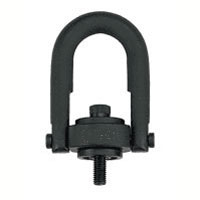
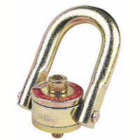
Lifting Point threaded VWBG |
|
|
|
Item No |
Thread |
W.L.L |
F |
A |
B |
T |
C |
D |
E |
G |
K |
Weigth |
Serial |
|
Size (M) |
Ton |
mm |
kg |
No. |
|
WBG200 |
M33 |
6 (7.5) |
50 |
23 |
86 |
208 |
50 |
90 |
80 |
96 |
80 |
5.6 |
8600150 |
|
WBG201 |
M33 |
6 (7.5) |
33-300 |
23 |
86 |
208 |
50 |
90 |
80 |
94 |
80 |
|
8600150 |
|
WBG202 |
M33x2#* |
6 (7.5) |
|
|
|
|
|
|
|
|
|
|
8600150 |
|
WBG203 |
M36 |
8 (10) |
54 |
22 |
86 |
208 |
50 |
90 |
|
94 |
80 |
4.67 |
7999059 |
|
WBG204 |
M36# |
8 (10) |
36-300 |
23 |
86 |
208 |
50 |
90 |
|
94 |
80 |
|
8600451 |
|
WBG205 |
M36x3#* |
8 (10) |
36-300 |
22 |
86 |
208 |
50 |
90 |
80 |
94 |
80 |
4.79 |
8600451 |
|
WBG206 |
M42 |
12 (13) |
63 |
26 |
111 |
234 |
65 |
98 |
|
95 |
85 |
6.1 |
7999044 |
|
WBG207 |
M42# |
12 (13) |
42-300 |
26 |
111 |
234 |
65 |
98 |
85 |
95 |
|
|
8600452 |
|
WBG208 |
M42x3#* |
12 (13) |
|
|
|
|
|
|
|
|
|
|
8600452 |
|
WBG209 |
M45 |
12 (15) |
67 |
26 |
111 |
234 |
65 |
98 |
|
95 |
85 |
6.24 |
7900455 |
|
WBG210 |
M48 |
13 (16) |
68 |
26 |
111 |
234 |
65 |
98 |
|
95 |
85 |
6.37 |
7999045 |
|
WBG211 |
M48# |
13 (16) |
48-300 |
26 |
111 |
234 |
65 |
98 |
85 |
95 |
|
|
8600453 |
|
WBG212 |
M48x3#* |
13 (16) |
|
|
|
|
|
|
|
|
|
|
8600453 |
|
WBG213 |
M52 |
14 (20) |
78 |
32 |
119 |
271 |
70 |
120 |
|
120 |
95 |
10.55 |
7901081 |
|
WBG214 |
M52 |
14 (20) |
52-300 |
32 |
119 |
271 |
70 |
120 |
|
120 |
95 |
|
8600158 |
|
WBG215 |
M56 |
16 (22) |
84 |
32 |
119 |
271 |
70 |
120 |
|
120 |
95 |
10.68 |
7999004 |
|
WBG216 |
M56x4#* |
16 (22) |
|
|
|
|
|
|
|
|
|
|
8600454 |
|
WBG217 |
M60 |
16 (22) |
90 |
32 |
119 |
271 |
70 |
120 |
|
120 |
95 |
11.37 |
8600454 |
|
WBG218 |
M60# |
16 (22) |
56-300 |
32 |
116 |
274 |
70 |
120 |
|
120 |
95 |
|
8600454 |
|
WBG219 |
M64 |
16 (25) |
94 |
32 |
119 |
274 |
70 |
120 |
|
120 |
95 |
11.4 |
7999043 |
|
WBG220 |
M64# |
16 (25) |
64-300 |
32 |
116 |
274 |
70 |
120 |
|
120 |
95 |
|
8600455 |
|
WBG221 |
M64x4#* |
16 (25) |
|
|
|
|
|
|
|
|
|
|
8600455 |
|
WBG222 |
M72 |
31.5(40) |
108 |
46 |
130 |
338 |
90 |
170 |
|
159 |
145 |
29.96 |
7900097 |
|
WBG223 |
M72# |
31.5(40) |
72-300 |
46 |
130 |
338 |
90 |
170 |
|
159 |
145 |
|
8600456 |
|
WBG224 |
M72x4#* |
31.5(40) |
72-300 |
46 |
130 |
338 |
90 |
170 |
|
159 |
145 |
29.96 |
8600456 |
|
WBG225 |
M80 |
35 (48) |
120 |
46 |
130 |
338 |
90 |
170 |
|
159 |
145 |
31.19 |
7900100 |
|
WBG226 |
M80# |
35 (48) |
80-300 |
46 |
130 |
338 |
90 |
170 |
|
159 |
145 |
|
8600457 |
|
WBG227 |
M80x4#* |
35 (48) |
80-300 |
46 |
130 |
338 |
90 |
170 |
|
159 |
145 |
31.19 |
8600457 |
|
WBG228 |
M90 |
40 (50) |
135 |
46 |
130 |
338 |
90 |
170 |
|
159 |
145 |
33.16 |
7995545 |
|
WBG229 |
M90 |
40 (50) |
90-300 |
46 |
130 |
338 |
90 |
170 |
|
159 |
145 |
|
8600458 |
|
WBG230 |
M90x4#* |
40 (50) |
|
|
|
|
|
|
|
|
|
|
8600157 |
|
WBG231 |
M100 |
40 (50) |
150 |
46 |
130 |
338 |
90 |
170 |
|
159 |
145 |
35.13 |
8600157 |
|
WBG232 |
M100# |
40 (50) |
90-300 |
46 |
130 |
338 |
90 |
170 |
|
159 |
145 |
|
8600157 | |
|
# : special thread (Indicate M size & F length uponrequest) |
| * : variable length (Indicate Length Upon Request),Vario |
|
For heavy loads which have to be turned and swivelled.
♣14. With ball bearings. Swivels under full load.
♣15.. Not suitable for permanent swivelling under full load, especially in 90° direction.
♣16. Loadable in any direction. Safety factor 4 : 1.
♣17. Suspension ring manufactured acc. EN 1677-4 grade 80 (100 % proof loaded).
♣18. S = max. allowed gap, see hints for Installation page 39.
♣19. VWBG: Wear marks in the main load directions 45°, 60° and 90°.
Safety notice:
Please provide plain bolting surface. The countersunk for the thread should be: thread diameter plus 4 mm (0,15 inch).
The base material of the workpiece must be capable to withstand the occurring lifting forces.
Minimum required material = S235JR/St 37 (1.0037).
*Caution:
During lifting, the ring of the lifting point can engage in any position. The embossed WLL is for the worst case scenario (see image X). If the ring is manually adjusted to the horizontal position, higher WLL values in brackets ( ) can be choosen (see image Y). In case of straight pull (see image Z: vertical load direction) Maximum WLL can be choosen. The nominal WLL can be increased acc. the load chart. |

| |
| ◆ Proof Testing |
|
There is no requirement to Proof Test RUD Products, either Bolt or Weldable after Installation if the user instructions for welding are carried out correctly. The welding should be carried out by a suitably qualified and competent welder/person.
The supporting structure, or the load, should be of adequate strength to take the stresses involved and this is the responsibility of the engineering designer or equivalent.
RUD Lifting and Lashing Products are Manufactured and conform to EN 1677. No further Proof Testing in the field is required. In fact it would be considered that the Product had been overloaded if a Load more than the recommended Working Load Limit had been applied.
RUD products should be regularly inspected in line with the requirements of LOLER and as per our user instructions at intervals decided by a competent person.
|
| ◆ Load Chart |
|
Method
of lifting |

|

|

|

|

|

|

|

|
|
Legs |
1 |
1 |
2 |
2 |
2 |
2 |
3 and 4 |
3 and 4 |
|
Angle<ß |
0° |
90° |
0° |
90° |
0-45° |
45-60° |
비대칭 |
0-45° |
45-60° |
비대칭 |
|
Factor |
- |
1 |
- |
2 |
1.4 |
1 |
1 |
2.1 |
1.5 |
1 |
|
Metric |
Lifting Point-Vario VWBG-V - Bolted and adjusted to the direction of pull |
|
M8 |
1 |
0.4 |
2 |
0.8 |
0.56 |
0.4 |
0.4 |
0.84 |
0.6 |
0.4 |
|
M10 |
1 |
0.4 |
2 |
0.8 |
0.56 |
0.4 |
0.4 |
0.84 |
0.6 |
0.4 |
|
M12 |
2 |
0.75 |
4 |
1.5 |
1 |
0.75 |
0.75 |
1.6 |
1.12 |
0.75 |
|
M14 |
|
|
|
|
|
|
|
|
|
|
|
M16 |
4 |
1.5 |
8 |
3 |
2.1 |
1.5 |
1.5 |
3.15 |
2.25 |
1.5 |
|
M18 |
|
|
|
|
|
|
|
|
|
|
|
M20 |
6 |
2.3 |
12 |
4.6 |
3.22 |
2.3 |
2.3 |
4.83 |
3.45 |
2.3 |
|
M22 |
6 |
2.3 |
12 |
4.6 |
3.22 |
2.3 |
2.3 |
4.83 |
3.45 |
2.3 |
|
M24 |
8 |
3.2 |
16 |
6.4 |
4.48 |
3.2 |
3.2 |
6.7 |
4.8 |
3.2 |
|
M27 |
|
|
|
|
|
|
|
|
|
|
|
M30 |
12 |
4.5 |
24 |
9 |
6.3 |
4.5 |
4.5 |
9.4 |
6.7 |
4.5 |
|
Metric |
Lifting Point threaded VWBG - Bolted and adjusted to the direction of pull |
|
M33 |
15 |
6 (7.5) |
30 |
12 (15) |
8.4 (10.5) |
6 (7.5) |
6 (7.5) |
12.6 (15.75) |
9 (11.25) |
6 (7.5) |
|
M36 |
15 |
8 (10) |
30 |
16 (20) |
11.2 (14) |
8 (10) |
8 (10) |
16.8 (21) |
12 (15) |
8 (10) |
|
M42 |
17 |
12 (13) |
34 |
24 (26) |
16.8 (18.2) |
12 (13) |
12 (13) |
25.2 (27.3) |
18 (19.5) |
12 (13) |
|
M45 |
18 |
12 (15) |
36 |
24 (30) |
16.8 (21) |
12 (15) |
12 (15) |
25.23 (31.5) |
18 (22.5) |
12 (15) |
|
M48 |
18 |
13 (16) |
36 |
26 (32) |
18.2 (22.4) |
13 (16) |
13 (16) |
27.3 (33.6) |
19.5 (24) |
13 (16) |
|
M52 |
25 |
14 (20) |
50 |
28 (40) |
19.6 (28) |
14 (20) |
14 (20) |
29.4 (42) |
21 (30) |
14 (20) |
|
M56 |
28 |
14 (20) |
56 |
32 (40) |
22.4 (28) |
14 (20) |
14 (20) |
29.4 (42) |
24 (30) |
14 (20) |
|
M60 |
28 |
16 (22) |
56 |
32 (44) |
22.4 (30.8) |
16 (22) |
16 (22) |
33.6 (46.2) |
24 (33) |
16 (22) |
|
M64 |
28 |
16 (25) |
56 |
32 (50) |
22.4 (35) |
16 (25) |
16 (25) |
33.6 (52.5) |
24 (37.5) |
16 (25) |
|
M72 |
50 |
31.5(40) |
100 |
63 (80) |
44.1 (56) |
31.5(40) |
31.5(40) |
66.15 (84) |
47.25 (60) |
31.5(40) |
|
M80 |
50 |
35 (48) |
100 |
70 (96) |
49 (67.2) |
35 (48) |
35 (48) |
73.5 (100.8) |
52.5 (72) |
35 (48) |
|
M90 |
50 |
40 (50) |
100 |
80 (100) |
56 (70) |
40 (50) |
40 (50) |
84 (105) |
60 (75) |
40 (50) |
|
M100 |
|
|
|
|
|
|
|
|
|
| |
|
* Hint: Stated WLL for 3-4 strands is only valid when it is guaranteed that the load is distributed equal to more than 2 strands. Otherwise the 2 strand values must be taken
ⒶATTENTION
Please mind at the use especially that the method of lifting does not get changed |
1 Safety instructions
ⒷATTENTION
Wrong assembled or damaged lifting points as well as improper use can lead to injuries of persons and damage of objects when load drops. Please inspect all lifting points before each use.
♣20. Not suitable for permanent turning operations under load.
Lifting point cannot be turned 90° to the bolt-on direction under full load.
♣21. The ball bearing resp. the bush bearing disc must not be disassembled.
♣22. The load ring must not be bend.
♣23. RUD VWBG-V lifting points must only be used by instructed and competent persons considering BGR 500 and
outside Germany noticing the country specific statutory regulations.
2 Intended use of VWBG
RUD VWBG-V lifting points must only be used for the assembly at the load or at lifting means.
They are intended to be hinged into lifting means and can be turned under load, but not under full load, especially not in the 90° direction. Not suitable for permanent turning operations under load.
RUD VWBG-V lifting points can also be used as lashing points to attach lashing means.
RUD VWGB-V lifting points must only be used in the hereby described operation purpose.
3 Assembly- and instruction manual
3.1 General information
♣24. Capability of temperature usage:
Usage at higher temperatures is not recommended due to the grease filling in the ball bearing.
Should this though be necessary, the working load limit (WLL) of the VWBG must be reduced as follows:
- -40°C up to 200°C no reduction
- 200°C up to 300°C minus 10 %
- 300°C up to 400°C minus 25 %
Temperatures exceeding 400°C are prohibited!
Please pay attention when using DIN EN 7042 (DIN 980) nuts the max. operation temperature of 150°C (acc. to DIN EN ISO 2320).
♣25. RUD VWBG lifting points must not be used with aggressive chemicals such as acids, alkaline solutions and their vapours.
♣26. Please mark mounting position of lifting point with a coloured contrast paintfor better visibility.
3.2 Hints for the assembly
Basically essential:
♣27. The material construction to which the lifting point will be attached should be of adequate strength to withstand forces during lifting without deformation.
The German testing authority BG, recommends the following minimum for the bolt lengths:
1 x M (thread diameter) in steel(min. quality 235JR [1.0037])
1.25 x M (thread diameter) in cast iron(e.g. GG 25)
2 x M (thread diameter) in aluminium
2.5 x M (thread diameter) in light alloys of low strength
(M = thread size/diameter, e.g. M20)
♣28. When lifting light metals, nonferrous metals and gray cast iron the thread has to be chosen in such a way that the WLL of the thread corresponds to the requirements of the base material.
♣29. The position of the lifting points must be carried out in such a way that unintended movement like turning or flipping will be avoided.
♣30. For single leg lifts,the lifting point should be vertically above the centre of gravity of the load.
♣31. For two leg lifts, the lifting points must be equidistant to/or above the centre of gravity of the load.
♣ For three and four leg lifts, the lifting points should be arranged symmetrical around the centre of gravity, in the same plane if possible.
♣32. Load symmetry:
Determine the necessary WLL of each lifting point for a symmetrical or an unsymmetrical load by using the following physical calculation formula:
W.L.L= G / n x cos ß
W.L.L= necessary W.L.L of lifting point / single strand
G = weight of load
n = number of load bearing strands
cos ß = inclination angle of single strand
Number of load bearing strands:
|
. |
Symmetric |
Unsymmetric |
|
Two Leg |
2 |
1 |
|
Three / Four Leg |
3 |
1 | Chart 1: Load bearing strands
♣33. A plane bolt-on surface (ØD) with a perpendicular thread hole must be guaranteed.
The thread must be carried out acc. to DIN 76 (countersink max. 1.05xd).
♣34. Tapped holes must be machined deep enough so that the bearing surface of the lifting point will be supported.
♣35. Due to the ball bearing it is sufficient for a single lift to tighten the VWBG until the bearing surface has support by using a spanner acc. to DIN 895resp. DIN 894, without using an extension. If the VWBG shall permanently installed at the load, tensioning must be carried out with a torque (+/- 10 %) according to chart 2.
♣36. The type VWBG-V can be supplied with different thread lengths (see Fvario in chart 2),
and the metric versions with washer und crack detected nut.
The assembly resp. the installation of bolts with different thread lengths is only allowed,
if camed out by either RUD or an authorized RUD distributor.
ⒸATTENTION
Disassembly of the ball bearing resp. the bush bearing disc carried out by the user is forbidden.
♣37. Check finally the correct assembly (see chapter 4, Inspection criteria).
3.3 User instructions
♣38. Check frequently and before each initial operation the whole lifting mean in regard of linger ability as a lifting mean, regarding corrosion, wear, deformation etc. (see chapter 4, Inspection criteria).
|
ⒹATTENTION
Wrong assembled or damaged lifting means as well as improper use can lead to injuries of persons and damage of objects when load falls.
Please inspect all lifting points before each use.
♣39. VWBGs are suitable for turning and flipping of loads. In doing so, all positions of the ring can occur. The stated WLL at the lifting point is given for the most inappropriatepossible case of operation (see picture 4 - part X). When ring has been adjusted manually (see picture Y) the higher (WLL) values from chart 3 can be used.
ⒺATTENTION
Pay attention during the usage that the load type will not be change
If the VWBG is will be loaded only perpendicular (in axial direction of the thread, see picture 4 - part Z) the corresponding WLL values from chart 3 (inclination angle 0°) can be used.
♣40. The ring of the manually adjusted VWBG can be pivoted by approx. 230° (see picture 1).
|
 |
ⒻATTENTION
The suspension ring resp. the attached lifting mean must rotate and pivot without interference during lifting and must neither have support at the load edge nor at the bottom part of the VWBG (see picture 2).
♣41. When lifting means (sling chains) are hinged or unhinged, no pinching, shearing or joint spots must occure during the handling. Avoid damage of lifting means resulting from sharp edges.
♣42. Leave direct danger zone as far as possible.
♣43. Watch always your hinged loads.
♣44. Avoid impulsive and tiltful loading.
ⒼATTENTION
Impulsive loading or vibration, especially at through hole connections with nuts, can lead to unintentional loosening.
Securing possibilities: liquid thread securing products f.e. Loctite (read manufacturer´s instruction) or form closed bolt securing such as a crown nut with split pin, lock nut etc. can be used.
Secure in general all lifting points which are installed permanently, e.g. with glue.
♣45. Please observe for the whole lifting mean the RUD sling chain safety instruction. |
 | 3.4 Hints for regular inspection
Lingering appropriateness of lifting means should be tested by a competent person, depending on the operational demands or at least once a year (see chapter 4 Inspection criteria). Depending on the operational demands, resulting from a numerous use, f.e. increased wear or corrosion, could make an earlier inspection necessary which means in a shorter interval than one year.
4 Inspection criteria
Observe and control the following points before each initial operation, in regular time intervals, after the assembly and after special incidents.
♣46. Correct bolt- and nut size plus thread engagement
♣47. Solid bolt fixture - Inspection of bolting torque
♣48. The bearing surface of the VWBG must lay plane and holohedral on the bolting area.
♣49. Completeness of the lifting point
♣50. Complete, readable WLL statements as well as manufacturer sign.
♣51. Deformation at load bearing components like base body, suspension ring and threaded pin.
♣52. Mechanical damage, like strong notches, especially in areas where tensile stress occurs.
♣53. Locking screw at the side must be tightened
♣54. Reduction of cross-section due to wear >10 % or when the wear lenses have been reached in the main load bearing directions
♣55. cracks or any other damage
♣56. Function and damage of bolt threads and nuts
♣57. Easy turning withoutjerk between upper and base part of the VWBG must be guaranteed.
♣58. The maximum allowance for clearance of s = 4 mm, between upper and base part must not be exceeded, respectively the proof groove in the ring connection must not be visible.
♣59. The maximum gap between upper and base part must not be exceeded:
- VWBG-V 0.3 - 0.45: max. 1.2 mm
- VWBG-V 0.6 - 2.0: max. 1.5 mm
- VWBG-V 3.5 - 5.0: max. 3.0 mm |

|

5 Hints for repairing
Repair work must only be carried out by a competent person at RUD or by a RUD trained and authorized service station, which has obtained the necessary knowledge and skills.
RUD-VWBGs are designed for a dynamical loading of 20.000 load cycles at nominal working load.
The BG recommends: At a high dynamic loading with high numbers of load cycles (continious work) the bearing stress acc. to FEM group 1Bm (M3 acc. to DIN 818-7) must be reduced.
|
|
♣ Renference : RUD GMBH - LiftingSafety
♣ Please feel free to call: 02-896-5656 or Fax: 02-896-5659 or contact us via e-mail(8965656@hanmail.net)
so our company can help you obtain the correct equipment for your applications. |
|
 |
|
|
|
|


 1호이스트링-varioVWBG-V 상세보기


