|
|
 |
|
 |
|
1ШЃРЬНКЦЎ...
|
|
|
 |
|
1ШЃРЬНКЦЎ...
|
|
|
 |
|
1ШЃРЬНКЦЎ...
|
|
|
 |
|
1ШЃРЬНКЦЎ...
|
|
|
 |
|
1ШЃРЬНКЦЎ...
|
|
|
 |
|
7ОЦРЬКМЦЎ
|
|
|
 |
|
1ШЃРЬНКЦЎ...
|
|
|
 |
|
1ШЃРЬНКЦЎ...
|
|
|
|
 |
1ШЃРЬНКЦЎИЕ-СпЗЎ
|
|
|
Ёп Metric Threads - Heavy Lift Swivel Hoist Rings |
|
Frame
size No |
item
No. |
W.L.L(kg)* |
Torque
in Nm |
Dimensions (mm) |
Weight
kg |
|
5:1 |
4:1 |
AЂд |
B |
C |
D |
E |
F |
G |
H |
|
1 |
HHM307 |
400 |
500 |
10 |
M8x1.25x40 |
15.2 |
93.7 |
24.6 |
15.7 |
11.2 |
57.7 |
35.1 |
0.3 |
|
1 |
HHM316 |
450 |
550 |
16 |
M10x1.50x40 |
15.2 |
93.7 |
24.6 |
15.7 |
11.2 |
57.7 |
35.1 |
0.3 |
|
2 |
HHM325 |
1050 |
1300 |
38 |
M12x1.75x55 |
15.5 |
162 |
49.8 |
31.8 |
19.1 |
107 |
63.5 |
1.5 |
|
2 |
HHM334 |
1900 |
2400 |
81 |
M16x2.00x65 |
25.5 |
162 |
49.8 |
31.8 |
19.1 |
107 |
63.5 |
1.5 |
|
2 |
HHM343 |
2150 |
2700 |
136 |
M20x2.50x70 |
30.5 |
162 |
49.8 |
31.8 |
19.1 |
107 |
63.5 |
1.6 |
|
3 |
HHM352 |
3000 |
3750 |
136 |
M20x2.50x80 |
25.4 |
220 |
75.2 |
41.4 |
25.4 |
159 |
82.6 |
4.6 |
|
3 |
HHM361 |
4200 |
5250 |
312 |
M24x3.00x90 |
35.4 |
220 |
75.2 |
41.4 |
25.4 |
159 |
82.6 |
4.8 |
|
4 |
HHM370 |
7000 |
8750 |
637 |
M30x3.50x140 |
66.2 |
285 |
94.2 |
50.8 |
31.8 |
199 |
102 |
9.7 |
|
4 |
HHM389 |
11000 |
13750 |
1005 |
M36x4.00x130 |
56.2 |
285 |
94.2 |
50.8 |
31.8 |
199 |
102 |
10 |
|
Ёп UNC Threads - Heavy Lift Swivel Hoist Rings |
|
Frame
size No |
item
No. |
W.L.L
(lbs)* |
Torque
in ft.lbs |
Dimensions (in) |
Weight
lbs |
|
AЂд |
B |
C |
D |
E |
F |
G |
H |
|
1 |
HHU002 |
800 |
7 |
5/16-18x1.50 |
0.52 |
3.69 |
0.97 |
0.62 |
0.44 |
2.27 |
1.38 |
0.6 |
|
1 |
HHU006 |
1000 |
12 |
3/8-16x1.50 |
0.52 |
3.69 |
0.97 |
0.62 |
0.44 |
2.27 |
1.38 |
0.62 |
|
2 |
HHU010 |
2500 |
28 |
1/2-13x2.25 |
0.69 |
6.26 |
1.96 |
1.25 |
0.62 |
4.2 |
2.5 |
3.05 |
|
2Ђг |
HHU014 |
2500 |
28 |
1/2-13x2.75 |
1.19 |
6.26 |
1.96 |
1.25 |
0.62 |
4.2 |
2.5 |
3.07 |
|
2 |
HHU018 |
4000 |
60 |
5/8-11x2.25 |
0.69 |
6.26 |
1.96 |
1.25 |
0.62 |
4.2 |
2.5 |
3.11 |
|
2Ђг |
HHU022 |
4000 |
60 |
5/8-11x3.00 |
1.44 |
6.26 |
1.96 |
1.25 |
0.62 |
4.2 |
2.5 |
3.18 |
|
2 |
HHU026 |
5000 |
100 |
3/4-10x2.50 |
0.94 |
6.26 |
1.96 |
1.25 |
0.62 |
4.2 |
2.5 |
3.24 |
|
2Ђг |
HHU030 |
5000 |
100 |
3/4-10x3.00 |
1.44 |
6.26 |
1.96 |
1.25 |
0.62 |
4.2 |
2.5 |
3.3 |
|
3 |
HHU034 |
7000** |
100 |
3/4-10x3.00 |
0.85 |
8.66 |
2.96 |
1.63 |
1 |
6.25 |
3.25 |
10.1 |
|
3Ђг |
HHU038 |
7000** |
100 |
3/4-10x4.00 |
1.85 |
8.66 |
2.96 |
1.63 |
1 |
6.25 |
3.25 |
10.2 |
|
3 |
HHU042 |
8000 |
160 |
7/8-9x3.00 |
0.85 |
8.66 |
2.96 |
1.63 |
1 |
6.24 |
3.25 |
10.2 |
|
3Ђг |
HHU046 |
8000 |
160 |
7/8-9x4.00 |
1.85 |
8.66 |
2.96 |
1.63 |
1 |
6.24 |
3.25 |
10.4 |
|
3 |
HHU050 |
10000 |
230 |
1-8x3.50 |
1.35 |
8.66 |
2.96 |
1.63 |
1 |
6.24 |
3.25 |
10.5 |
|
3Ђг |
HHU054 |
10000 |
230 |
1-8x4.50 |
2.35 |
8.66 |
2.96 |
1.63 |
1 |
6.24 |
3.25 |
10.7 |
|
4 |
HHU058 |
15000 |
470 |
1-1/4-7x5.00 |
2.09 |
11.21 |
3.71 |
2 |
1.25 |
7.82 |
4 |
21.9 |
|
4 |
HHU062 |
24000 |
800 |
1-1/2-6x5.50 |
2.59 |
11.21 |
3.71 |
2 |
1.25 |
7.82 |
4 |
23 |
|
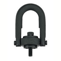
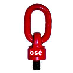
ЂР Forged bail provides the following:
ЂР Easily readable "Raised Lettering" showing the name Crosby or "CG" and PIC Code for material traceability.
ЂР Greater durability providing the increased "Toughness" desired in potentially abusive field conditions.
ЂР Larger opening than standard Hoist Ring bail.
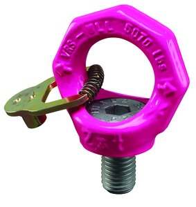
ЂР Top washer is color coded for easy identification (Red for UNC threads and Silver for Metric threads)
ЂР The Working Load Limit and Recommended Torque value are permanently stamped into each washer.
ЂР Individually Proof Tested to 2-1/2 times Working Load Limit.
ЂР Available in both UNC Thread and Metric Thread style.
ЂР BOLT SIZE IDENTIFICATION: The size of the bolt will be stated as in the drawing below. Illustration shows meaning of each dimension given.
* Ultimate Load is 5 times the Working Load Limit. ** Ultimate Load is 4.5 times the Working Load Limit for 7000# Hoist Ring when tested in 90 degree orientation.
*** Individually proof loaded to 2-1/2 times the Working Load Limit based on the 4:1 design factor. Ђг Long Bolts are designed to be used with soft metal (i.e., aluminum) work piece. While the long bolts may also be used with ferrous metal (i.e.,steel & iron) work piece, short bolts are designed for ferrous work pieces only.
Ђд Bolt specification is a Grade 8 Alloy socket head cap screw to ASTM A 574. ЂдЂд Bolt specification is a Grade 12.9 Alloy socket head cap screw to DIN 912.
NOTE: The tightening torque values shown are based upon threads being clean, dry and free of lubrication. |
|
 |
|
|
|
|


 1ШЃРЬНКЦЎИЕ-СпЗЎ ЛѓММКИБт

