|
|
 |
|
 |
|
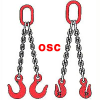
1체인슬링-...
|
|
|
 |
|
1체인슬링-...
|
|
|
 |
|
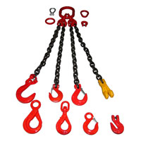
1체인슬링-...
|
|
|
 |
|
1링크-정방...
|
|
|
 |
|
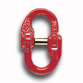
2컨넥터
|
|
|
 |
|
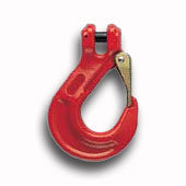
3후크-그레...
|
|
|
 |
|
1체인스링...
|
|
|
 |
|
1체인슬링...
|
|
|
|
 |
1체인슬링-1줄
|
|
| Grade 80 Sling Chain System 오성산업 |
|
|
|

|

|
|
|
|

|
|
|
Angle of Indication |
- |
- |
<45ø |
45ø-60ø |
<45ø |
45ø-60ø |
<45ø |
45ø-60ø |
- |
<45ø |
45ø-60ø |
|
Load Factor |
1 |
0.8 |
1.4 |
1 |
1.12 |
0.8 |
2.1 |
1.5 |
1.6 |
1.4 |
2.1 |
|
Grade |
D |
Load Capacity [Ton] - OSC.CO.KR |
|
G100 |
5 |
1 |
0.8 |
1.4 |
1 |
1.120 |
0.8 |
2 |
1.5 |
1.6 |
1.4 |
2 |
|
G80 |
5 |
0.8 |
0.64 |
1.12 |
8 |
9 |
0.64 |
1.6 |
1.18 |
1.25 |
1.12 |
1.6 |
|
G100 |
6 |
1.4 |
1.12 |
2 |
1.4 |
1.6 |
1.12 |
3 |
2.12 |
2.24 |
2 |
3 |
|
G80 |
6 |
1.12 |
9 |
1.6 |
1.12 |
1.25 |
9 |
2.36 |
1.7 |
1.8 |
1.6 |
2.36 |
|
G100 |
7 |
1.9 |
1.5 |
2.65 |
1.9 |
2.12 |
1.5 |
4 |
2.8 |
3 |
2.65 |
4 |
|
G80 |
7 |
1.5 |
1.2 |
2.12 |
1.5 |
1.7 |
1.2 |
3.15 |
2.24 |
2.5 |
2.12 |
3.15 |
|
G100 |
8 |
2.5 |
2 |
3.55 |
2.5 |
2.8 |
2 |
5.3 |
3.75 |
4 |
3.55 |
5.3 |
|
G80 |
8 |
2 |
1.6 |
2.8 |
2 |
2.24 |
1.6 |
4.25 |
3 |
3.15 |
2.8 |
4.25 |
|
G100 |
10 |
4 |
3.15 |
5.6 |
4 |
4.25 |
3.15 |
8 |
6 |
6.3 |
5.6 |
8 |
|
G80 |
10 |
3.15 |
2.5 |
4.25 |
3.15 |
3.55 |
2.5 |
6.7 |
4.75 |
5 |
4.25 |
6.7 |
|
G100 |
13 |
6.7 |
5.3 |
9.5 |
6.7 |
7.5 |
5.3 |
14 |
10 |
10.6 |
9.5 |
14 |
|
G80 |
13 |
5.3 |
4.25 |
7.5 |
5.3 |
5.9 |
4.25 |
11.2 |
8 |
8.5 |
7.5 |
11.2 |
|
G100 |
16 |
10 |
8 |
14 |
10 |
11.2 |
8 |
21.2 |
15 |
16 |
14 |
21.2 |
|
G80 |
16 |
8 |
6.3 |
11.2 |
8 |
9 |
6.3 |
17 |
11.8 |
12.5 |
11.2 |
17 |
|
G100 |
20 |
14 |
11.2 |
20 |
14 |
16 |
11.2 |
30 |
21.2 |
22.4 |
20 |
30 |
|
G80 |
20 |
12.5 |
10 |
17.5 |
12.5 |
14 |
10 |
26.3 |
18.8 |
20 |
17.5 |
26.3 |
|
G100 |
22 |
19 |
15 |
26.5 |
19 |
21.2 |
15 |
40 |
28 |
30 |
26.5 |
40 |
|
G80 |
22 |
15 |
12 |
21.2 |
15 |
17 |
12 |
31.5 |
22.4 |
23.6 |
21.2 |
31.5 |
|
G80 |
26 |
21.2 |
16.95 |
30 |
21.2 |
23.7 |
16.95 |
45 |
31.5 |
33.5 |
30 |
45 |
|
G80 |
32 |
31.5 |
25.2 |
45 |
31.5 |
35.2 |
25.2 |
67 |
47.5 |
50 |
45 |
67 | |
|
Grade 80 Working Load Limits (Ton) |
|
CHAIN
Dia
mm |
Single leg slings |
Slings of 2,3 or 4 legs |
Endless Slings |

Straight
Sling |

Adjustable
Sling |

Reeved
Sling |

Straight sling |

Reeved sling |

Basket sling |

Reeved
Sling |
|
60º |
90º |
120º |
60º |
90º |
120º |
60º |
90º |
120º |
|
|
0.5 |
0.5 |
0.4 |
0.85 |
0.7 |
0.5 |
0.65 |
0.5 |
0.4 |
0.65 |
0.5 |
0.4 |
0.75 |
|
|
1.1 |
1.1 |
0.8 |
1.9 |
1.6 |
1.1 |
1.5 |
1.2 |
0.8 |
1.5 |
1.2 |
0.8 |
1.7 |
|
7 |
1.6 |
1.2 |
1.2 |
2.7 |
2.2 |
1.6 |
2.0 |
1.7 |
1.2 |
2.0 |
1.7 |
1.2 |
2.4 |
|
|
2.0 |
2.0 |
1.5 |
3.5 |
2.8 |
2.0 |
2.6 |
2.1 |
1.5 |
2.6 |
2.1 |
1.5 |
3.0 |
|
|
3.2 |
3.2 |
2.4 |
5.5 |
4.5 |
3.2 |
4.1 |
3.4 |
2.4 |
4.1 |
3.4 |
2.4 |
4.8 |
|
|
5.3 |
5.3 |
4.0 |
9.2 |
7.5 |
5.3 |
6.9 |
5.6 |
4.0 |
6.9 |
5.6 |
4.0 |
8.0 |
|
|
8.0 |
8.0 |
6.0 |
13.8 |
11.3 |
8.0 |
10.4 |
8.5 |
6.0 |
10.4 |
8.5 |
6.0 |
12.0 |
|
|
12.5 |
9.4 |
9.4 |
21.6 |
17.6 |
12.5 |
16.3 |
13.3 |
9.4 |
16.3 |
13.3 |
9.4 |
18.8 |
|
|
15.0 |
11.3 |
11.3 |
26.0 |
21.2 |
15.0 |
19.5 |
15.9 |
11.3 |
19.5 |
15.9 |
11.3 |
22.5 |
|
|
21.2 |
15.9 |
15.9 |
36.7 |
29.9 |
21.2 |
27.6 |
22.5 |
15.9 |
27.6 |
22.5 |
15.9 |
31.8 |
|
|
31.5 |
23.6 |
23.6 |
54.5 |
44.4 |
31.5 |
41.0 |
33.4 |
23.6 |
41.0 |
33.4 |
23.6 |
47.3 |
1. - Do note exceed Safe Working Loads
2. - Do note exceed an Angle of 120°
3. - Do not use above 400°C
4. - Do not Shock Load | |
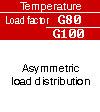
|
Temperature |
|
|
|
|
|
|
Angle |
>45ø |
45ø-60ø |
>45ø |
45ø-60ø |
>45ø |
45ø-60ø |
|
Load factor |
0,7 |
1 |
0.7 |
1 |
0,7 |
0.7 |
|
|
|
|
|
|
Shock |
slight shocks |
medium shocks |
strong shocks |
|
Load factor |
1 |
0,7 |
not permissible | |
|
Working Load Limits |
|
Tips on Working Load Limits |
|
Actual sling working load limit
= (Factor) x (Working load limit) |
♣ Sling angles have a direct and oftentimes dramatic affect on the working load limit of a sling.
♣ This angle, which is measured between a horizontal line and the sling leg or body, may apply to a single leg sling in an angled vertical or basket hitch, or a multi-legged bridle sling.
♣ Anytime pull is exerted at an angle on a leg, the tension, or stress, on each leg is increased.
♣ It is critical that working load limits be reduced in order to account for sling angles.
♣ Angles less than 45 degrees are not recommended and those below 30 degrees should be avoided whenever possible.
♣ Use the formula and chart shown below to calculate the reduction in working load limits caused by various sling angles.
♣ Reference : ANSI B30.9 and OSHA 1910.184.
♣ OH SUNG Chain Co.
Please feel free to call: 02-896-5656 or Fax: 02-896-5659
or contact us via e-mail (ohand@hanmail.net)
so our company can help you obtain the correct equipment for your applications. |
|
Sling Angles
in Degrees |
Factor |
|
90 |
1 |
|
85 |
0.996 |
|
80 |
0.985 |
|
75 |
0.966 |
|
70 |
0.940 |
|
65 |
0.906 |
|
60 |
0.866 |
|
55 |
0.819 |
|
50 |
0.766 |
|
45 |
0.707 |
|
40 |
0.643 |
|
35 |
0.574 |
|
30 |
0.500 |
|
25 |
0.432 |
|
20 |
0.342 |
|
15 |
0.259 | |
|
HOW TO ORDER CHAIN SLINGS |
1- Determine the maximum load to be lifted by the chain sling you are ordering.
2- Choose the proper type of chain sling (single, double, etc.) which the size, shape and weight of the load dictate.
3- Estimate the approximate angle to the load in which the legs of the sling will be positioned for operation.
4- Select the proper attachments for your sling.
5- Determine the overall reach from bearing point on masterlink to bearing point on attachment.
6- Refer to the Working Load Limit Chart and to your pre-determined angle of the type sling you have selected.
7- Choose the chain size that meets your requirements.
8- When entering your order be sure you give complete information as to the size, reach and attachments required.
Note: Angle to the load an multiple leg slings will be 60° or greater as long as the distance between lifting eyes of load is NOT greater than reach shown on identification tag. |
|
CARE, USE AND INSPECTION |
The life and strength of Sling chain slings depend on proper inspection, maintenance and use.
For additional information, refer to ANSI B30.9 and OSHA 1910.184. |
|
Care |
Chain requires careful storage and regular maintenance;
♣ Store chains on an A frame in a clean, dry place.
♣ To avoid corrosion, oil chains before prolonged storage.
♣ Do not heat Alloy 80 chain; this will alter its thermal treatment.
♣ Do not plate or change surface finish of chain. |
|
Use |
To protect both operators and materials, observe these precautions when using chain slin
♣ Before use, inspect chain and attachments following the instructions under "Inspection" below.
♣ Do not exceed working load limit. Any of the factors listed here can reduce the load the chain will hold:
♣ Acceleration in rate of load application can produce dangerous overloading.
♣ Variation in the angle of the load to the sling - as the angle decreases, the working load of the sling will increase.
♣ Twisting, knotting or kinking- subjects links to unusualloading, decreasing the working load of the sling.
♣ Use for purposes other than those for which slings are intended can reduce the working load of the sling.
♣ Free chain of all twists, knots and kinks.
♣ Center load in hook(s); hook latches must not support load.
♣ Avoid sudden jerks when lifting and lowering.
♣ Balance all loads; avoid tipping of loads. Use pads around sharp corners.
♣ Do not drop load on chains.
♣ Match the size and working load limit of attachments such as hooks or ringsto the size and working load limit of the chain.
♣ For overhead lifting, use only alloy chain and attachments (grade 80). |
|
Inspection |
It is import!ant both to inspect chain slings regularly and to keep a record of all chain inspections. Follow this guide for such an inspection system;
♣ Before inspecting, clean chains with a non-acid/noncaustic solvent so that marks, nicks, wear and other defects are visible.
♣ Inspect each link for these conditions.
♣ Twists or bends.
♣ Nicks or gouges.
♣ Excessive wear at bearing points.
♣ Stretch.
♣ Distorted or damaged master links, coupling links or attachments; especially those spread in throat opening of hooks.
♣ Mark plainly with paint each link or attachment showing any of the conditions listed hereto indicate rejection; remove from service until properly repaired. |
|
Wear Allowances of Alloy 80 Chains |
Measure cross section at link ends to determine wear.
If chain is worn to less than the minimum allow
| mm |
Maximum Allowable Wear |
Minimum Thickness Allowable at Link Ends* |
| 7 |
1.1684 |
5.1562 |
| 10 |
1.9812 |
7.1374 |
| 13 |
2.7686 |
8.7122 |
| 16 |
3.5560 |
10.6934 |
| 20 |
3.9624 |
13.4874 |
| 22 |
4.3434 |
15.8750 |
| 26 |
4.7498 |
18.6436 |
| 32 |
6.3500 |
23.0124 |
| *Applies to Alloy Grade 80 chain only. | |
|
USE OF CHAIN UNDER HEAT CONDITIONS |
When the chain itself is heated to temperatures shown here, working load limits should be reduced as indicated.
| Temperature of Chain |
Reduction in working Load Limit while heated* |
Permanent reduction in Working Load Limit** |
| 260°c |
none |
none |
| 315°c |
10% |
none |
| 371°c |
50% |
none |
| 427°c |
30% |
none |
| 482°c |
40% |
10% |
| 538°c |
50% |
20% | *While chain is at temperature shown in first column.
**When chain is used at room temperature after having been heated to temperatures shown in first column. |
|
CERTIFICATE OF TEST AND IDENTIFICATION |
The identification tag found on the master coupling link of each chain sling contains this information.
Grade Size Reach Type Working load limit (at a specific angle of lift) Serial number |
|
CHAIN SLINGS (Working Load Limited) |
| Single Chain Sling |
Double Chain Sling |
Triple & Quad Chain Sling |
Chain
Dia(mm) |
W.L.L
ton |
Chain
Dia(mm) |
WLL
60° |
WLL
45° |
WLL
30° |
Chain
Dia(mm) |
WLL
60° |
WLL
45° |
WLL
30° |
| 7 |
1.59 |
7 |
2.77 |
2.22 |
1.59 |
7 |
4.13 |
3.36 |
2.36 |
| 10 |
3.22 |
10 |
5.58 |
4.55 |
3.22 |
10 |
8.35 |
6.85 |
4.81 |
| 13 |
5.44 |
13 |
9.43 |
7.71 |
5.44 |
13 |
9.62 |
11.57 |
8.16 |
| 16 |
8.21 |
16 |
14.20 |
11.61 |
8.21 |
16 |
21.32 |
17.42 |
12.29 |
| 20 |
12.84 |
20 |
22.03 |
18.14 |
12.84 |
20 |
33.33 |
27.21 |
19.23 |
| 22 |
15.51 |
22 |
26.85 |
21.95 |
15.51 |
22 |
40.32 |
32.88 |
23.27 |
| 26 |
21.64 |
26 |
37.47 |
30.57 |
21.64 |
26 |
56.20 |
45.90 |
32.43 |
| 32 |
32.79 |
32 |
56.79 |
46.36 |
32.79 |
32 |
85.18 |
69.58 |
49.17 | |
|
체인 사용법 |
|
Caution |
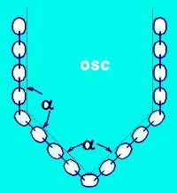 |
♣ Do not bend chain horizontally.
For spin suspension, the following table is the standard.
♣ Strength Efficiency of suspended Load's Angle
|
Suspension Angle |
Above 90o |
45o |
30o |
|
Strength Efficiency(%) |
60 |
50 |
45 | |
|
♣ Prevention of heat effects on the chain.
When the temperature is 400° to 500° the impact value by blue brittleness reduces.
♣ Efficiency of Used Load Under High-temperature Work. |
|
|
-40o to 100o |
100o to 200o |
200o to 300o |
300o to 350o |
350o to 400o |
400o to 450o |
more than 450o |
|
JIS-V |
100 |
90 |
75 |
65 |
60 |
Not for use |
Not for use |
|
S-T |
100 |
100 |
100 |
80 |
70 |
60 |
Not for use | |
|
Caution |
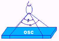 |
Make the angle of suspension as small as possible. If angle ß is more than 300, the slide will result. (In this event, use the beam suspension.)
Strength Efficiency of The Suspension Angle a (alpha)
| Suspension Angle |
30° |
45° |
65° |
90° |
| Strength Efficiency (%) |
96 |
92 |
86 |
70 | |
|
♣ If more than single sling, put weight of load equally. Do not twist the chain.
♣ While the suspension work, or while you work around the place where the chain could be earth,
do not conduct a welding job (it will cause arcstrike).
♣ When cutting the chain, use a high-speed cutter in order to prevent heat effects (gas cutting is not advised).
♣ Regular check-ups along the following standard is advised. |
|
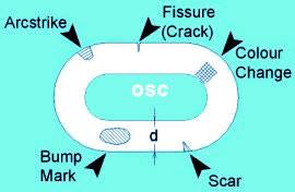
Inspection & Abandonment Standard |
 |
|
Inspection
Parts |
Standard |
Repairs & Counter-measures |
|
Arcstrike |
Small arcstrike is a mortal wound. |
Abandon |
|
Fissure |
As Above |
If its fissure depth is less than depth d X0.05, use grinder or file to smoothen it. |
|
Scar |
Depth Fused Part max. 0.07d. Others max. 0.1d |
Same as fissure |
|
Discoloration |
Gray & deep blue are disapproved |
As a result of heat, dis-coloration occurs. | |
|
|
|
|
Inspection Parts |
Standard |
Repairs & Counter-measures |
|
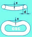
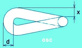
Bend |
x = max.0.1d |
When the bend or twist occurs, it is believed to be caused by concentrated load. Choose a suitable chain. |
|
Twist |
x = max.0.1d | |
 |
|
Inspection Parts |
Standard |
Repairs & Counter-measures |
|
Wear |
x = max.0.1d |
If it reaches the standard situation in a short period of time,
it is caused by dust or overload. |
|
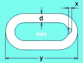
Elongation |
y = max.1.05P |
If pitch of the link is elongated,
it is a sign of overload.
Replace the chain. | |
|
|
|
|
|
Fall Of Breaking Load By Planting Or Painting |
|
Plating
♣ As a result of different plating temperature and tempering temperature or other factors, the plated goods sometimes weaken by about 15%. As strong chain plating is special, please refer to us. |
|
Painting
♣ If testing is carried out while paint or oil is stuck on the chain, strength of chain may fall by a maximum of 8%. Oil must be removed before test-using. (Breaking elongation of chain will be reduced by oil.). Elimination of oils is compulsory as stated in ISO. Test regulations. During practical use, there will be no occurrence of such problems as paint are removed during use.
♣ Breaking load values in our catalogue are those tested with unpainted products.
♣ Reference : ANSI B30.9 and OSHA 1910.184, CM,SKS |
|
OH SUNG Chain Co.
Please feel free to call: 02-896-5656 or Fax: 02-896-5659 or contact us via e-mail (8965656@hanmail.net)
so our company can help you obtain the correct equipment for your applications. |
|
 |
|
|
|
|


 1체인슬링-1줄 상세보기