|
|
 |
|
 |
|
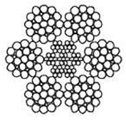
일반연 로...
|
|
|
 |
|
평행연 로...
|
|
|
 |
|
비자전로프...
|
|
|
 |
|
A C 로프▶...
|
|
|
 |
|
엘리베이터...
|
|
|
 |
|
스텐와이어
|
|
|
 |
|
코팅와이어
|
|
|
|
 |
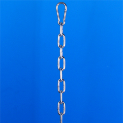
기타 로프
|
|
|
OSHA ( 미국 산업 안전 보건청 ) Health & Safety Construction-related Regulations - H |
|
OSHA Construction Regulations Page-( Subpart H - Materials Handling, Storage, Use, and Disposal ) |
|
OSHA 1926.251 - Rigging equipment for material handling. |
|
1. (a) General. |
|
2. (c) Wire Rope. |
|
3. (d) Natural Rope,and Synthetic Fiber |
|
4. (e) Synthetic Webbing (Nylon, Polyster, Polypropylene) |
|
5. (f) Shackle and Hooks. |
|
6. Table H-1 Working Load Limit for Alloy Steel Chain Slings |
|
7. Table H-2 Maximum Allowable Wear any Point of Link. |
|
8. Table H-3 Capacities for 1-Leg Slings. |
|
9. Table H-4. Capacities for 1-Leg Slings. |
|
10. Table H-5. Capacities for 1-Leg Slings. |
|
11. Table H-6. Capacities for 1-Leg Slings. |
|
12. Table H-7. Capacities for 2 ~ 3 Leg Bridle Slings. |
|
13. Table H-8. Capacities for 2 ~ 3 Leg Bridle Slings. |
|
14. Table H-9. Capacities for 2 ~ 3 Leg Bridle Slings. |
|
15. Table H-10. Capacities for 2 ~ 3 Leg Bridle Slings. |
|
16. Table H-11. Capacities for Strand Laid Grommet (Hand Tucked). |
|
17. Table H-12. Capacities for Strand Laid Grommet (Hand Tucked). |
|
18. Table H-13. Capacities for Strand Laid Endless Slings (Mechanical Joint) |
|
19. Table H-14. Capacities for Cable Laid Endless Slings (Mechanical Joint) |
|
20. Table H-15. Manila Rope Slings. |
|
21. Table H-16. Nylon Rope Slings. |
|
22. Table H-17. Polyester Rope Slings. |
|
23. Table H-18. Polypropylene Rope Slings. |
|
24. Table H-19. Safe Working Loads for Shackles. |
|
25. Table H-20. Number and Spacing of U-bolt Wire Rope Clips |
|
(a) General. |
|
(a1) Rigging equipment for material handling shall be inspected prior to use on each shift and as necessary during its use to ensure that it is safe. Defective rigging equipment shall be removed from service.
(a2) Rigging equipment shall not be loaded in excess of its recommended safe working load, as prescribed in Tables H-1 through H-20 in this subpart, following 1926.252(e) for the specific equipment.
(a3) Rigging equipment, when not in use, shall be removed from the immediate work area so as not to present a hazard to employees.
(a4) Special custom design grabs, hooks, clamps, or other lifting accessories, for such units as modular panels, prefabricated structures and similar materials, shall be marked to indicate the safe working loads and shall be proof-tested prior to use to 125 percent of their rated load.
(a5) Scope. This section applies to slings used in conjunction with other material handling equipment for the movement of material by hoisting, in employments covered by this part. The types of slings covered are those made from alloy steel chain, wire rope, metal mesh, natural or synthetic fiber rope (conventional three strand construction), and synthetic web (nylon, polyester, and polypropylene).
(a6) Inspections. Each day before being used, the sling and all fastenings and attachments shall be inspected for damage or defects by a competent person designated by the employer. Additional inspections shall be performed during sling use, where service conditions warrant. Damaged or defective slings shall be immediately removed from service. |
|
(c) Wire rope. |
|
(c1) Tables H-3 through H-14 shall be used to determine the safe working loads of various sizes and classifications of improved plow steel wire rope and wire rope slings with various types of terminals. For sizes, classifications, and grades not included in these tables, the safe working load recommended by the manufacturer for specific, identifiable products shall be followed, provided that a safety factor of not less than 5 is maintained.
(c2) Protruding ends of strands in splices on slings and bridles shall be covered or blunted.
(c3) Wire rope shall not be secured by knots, except on haul back lines on scrapers.
(c4) The following limitations shall apply to the use of wire rope:
(c4-1) An eye splice made in any wire rope shall have not less than three full tucks. However, this requirement shall not operate to preclude the use of another form of splice or connection which can be shown to be as efficient and which is not otherwise prohibited.
(c4-2) Except for eye splices in the ends of wires and for endless rope slings, each wire rope used in hoisting or lowering, or in pulling loads, shall consist of one continuous piece without knot or splice.
(c4-3) Eyes in wire rope bridles, slings, or bull wires shall not be formed by wire rope clips or knots.
(c4-4) Wire rope shall not be used if, in any length of eight diameters, the total number of visible broken wires exceeds 10 percent of the total number of wires, or if the rope shows other signs of excessive wear, corrosion, or defect.
(c5) When U-bolt wire rope clips are used to form eyes, Table H-20 shall be used to determine the number and spacing of clips.
(c5-1) When used for eye splices, the U-bolt shall be applied so that the "U" section is in contact with the dead end of the rope.
(c6) Slings shall not be shortened with knots or bolts or other makeshift devices.
(c7) Sling legs shall not be kinked.
(c8) Slings used in a basket hitch shall have the loads balanced to prevent slippage.
(c9) Slings shall be padded or protected from the sharp edges of their loads.
(c10) Hands or fingers shall not be placed between the sling and its load while the sling is being tightened around the load.
(c11) Shock loading is prohibited.
(c12) A sling shall not be pulled from under a load when the load is resting on the sling.
(c13) Minimum sling lengths.
(c13-1) Cable laid and 6 X 19 and 6 X 37 slings shall have minimum clear length of wire rope 10 times the component rope diameter between splices, sleeves or end fittings.
(c13-2) Braided slings shall have a minimum clear length of wire rope 40 times the component rope diameter between the loops or end fittings.
(c13-3) Cable laid grommets, strand laid grommets and endless slings shall have a minimum circumferential length of 96 times their body diameter.
(c14) Safe operating temperatures. Fiber core wire rope slings of all grades shall be permanently removed from service if they are exposed to temperatures in excess of 200 deg. F (93.33 deg. C). When nonfiber core wire rope slings of any grade are used at temperatures above 400 deg. F (204.44 deg. C) or below minus 60 deg. F (15.55 deg. C), recommendations of the sling manufacturer regarding use at that temperature shall be followed.
(c15) End attachments.
(c15-1) Welding of end attachments, except covers to thimbles, shall be performed prior to the assembly of the sling.
(c15-2) All welded end attachments shall not be used unless proof tested by the manufacturer or equivalent entity at twice their rated capacity prior to initial use. The employer shall retain a certificate of proof test, and make it available for examination. |
|
(d) Natural rope, and synthetic fiber. |
|
(d1) General. When using natural or synthetic fiber rope slings, Tables H-15, 16, 17, and 18 shall apply.
(d2) All splices in rope slings provided by the employer shall be made in accordance with fiber rope manufacturers recommendations.
(d2-1) In manila rope, eye splices shall contain at least three full tucks, and short splices shall contain at least six full tucks (three on each side of the center line of the splice).
(d2-2) In layed synthetic fiber rope, eye splices shall contain at least four full tucks, and short splices shall contain at least eight full tucks (four on each side of the center line of the splice).
(d2-3) Strand end tails shall not be trimmed short (flush with the surface of the rope) immediately adjacent to the full tucks. This precaution applies to both eye and short splices and all types of fiber rope. For fiber ropes under 1-inch diameter, the tails shall project at least six rope diameters beyond the last full tuck. For fiber ropes 1-inch diameter and larger, the tails shall project at least 6 inches beyond the last full tuck. In applications where the projecting tails may be objectionable, the tails shall be tapered and spliced into the body of the rope using at least two additional tucks (which will require a tail length of approximately six rope diameters beyond the last full tuck).
(d2-4) For all eye splices, the eye shall be sufficiently large to provide an included angle of not greater than 60 deg. at the splice when the eye is placed over the load or support.
(d2-5) Knots shall not be used in lieu of splices.
(d3) Safe operating temperatures. Natural and synthetic fiber rope slings, except for wet frozen slings, may be used in a temperature range from minus 20 deg. F (-28.88 deg. C) to plus 180 deg. F (82.2 deg. C) without decreasing the working load limit. For operations outside this temperature range and for wet frozen slings, the sling manufacturer's recommendations shall be followed.
(d4) Splicing. Spliced fiber rope slings shall not be used unless they have been spliced in accordance with the following minimum requirements and in accordance with any additional recommendations of the manufacturer:
(d4-1) In manila rope, eye splices shall consist of at least three full tucks, and short splices shall consist of at least six full tucks, three on each side of the splice center line.
(d4-2) In synthetic fiber rope, eye splices shall consist of at least four full tucks, and short splices shall consist of at least eight full tucks, four on each side of the center line.
(d4-3) Strand end tails shall not be trimmed flush with the surface of the rope immediately adjacent to the full tucks. This applies to all types of fiber rope and both eye and short splices. For fiber rope under 1 inch (2.54 cm) in diameter, the tail shall project at least six rope diameters beyond the last full tuck. For fiber rope 1 inch (2.54 cm) in diameter and larger, the tail shall project at least 6 inches (15.24 cm) beyond the last full tuck. Where a projecting tail interferes with the use of the sling, the tail shall be tapered and spliced into the body of the rope using at lest two additional tucks (which will require a tail length of approximately six rope diameters beyond the last full tuck).
(d4-4) Fiber rope slings shall have a minimum clear length of rope between eye splices equal to 10 times the rope diameter.
(d4-5) Knots shall not be used in lieu of splices.
(d4-6) Clamps not designed specifically for fiber ropes shall not be used for splicing.
(d4-7) For all eye splices, the eye shall be of such size to provide an included angle of not greater than 60 degrees at the splice when the eye is placed over the load or support.
(d5) End attachments. Fiber rope slings shall not be used if end attachments in contact with the rope have sharp edges or projections.
(d6) Removal from service. Natural and synthetic fiber rope slings shall be immediately removed from service if any of the following conditions are present:
(d6-1) Abnormal wear.
(d6-2) Powdered fiber between strands.
(d6-3) Broken or cut fibers.
(d6-4) Variations in the size or roundness of strands.
(d6-5) Discoloration or rotting.
(d6-6) Distortion of hardware in the sling. |
|
(e) Synthetic webbing (nylon, polyester, and polypropylene). |
|
(e1) The employer shall have each synthetic web sling marked or coded to show:
(e1-1) Name or trademark of manufacturer.
(e1-2) Rated capacities for the type of hitch.
(e1-3) Type of material.
(e2) Rated capacity shall not be exceeded.
(e3) Webbing. Synthetic webbing shall be of uniform thickness and width and selvage edges shall not be split from the webbing's width.
(e4) Fittings. Fittings shall be:
(e4-1) Of a minimum breaking strength equal to that of the sling; and
(e4-2) Free of all sharp edges that could in any way damage the webbing.
(e5) Attachment of end fittings to webbing and formation of eyes. Stitching shall be the only method used to attach end fittings to webbing and to form eyes. The thread shall be in an even pattern and contain a sufficient number of stitches to develop the full breaking strength of the sling.
(e6) Environmental conditions. When synthetic web slings are used, the following precautions shall be taken:
(e6-1) Nylon web slings shall not be used where fumes, vapors, sprays, mists or liquids of acids or phenolics are present.
(e6-2) Polyester and polypropylene web slings shall not be used where fumes, vapors, sprays, mists or liquids of caustics are present.
(e6-3) Web slings with aluminum fittings shall not be used where fumes, vapors, sprays, mists or liquids of caustics are present.
(e7) Safe operating temperatures. Synthetic web slings of polyester and nylon shall not be used at temperatures in excess of 180 deg. F (82.2 deg. C). Polypropylene web slings shall not be used at temperatures in excess of 200 deg. F (93.33 deg. C).
(e8) Removal from service. Synthetic web slings shall be immediately removed from service if any of the following conditions are present:
(e8-1) Acid or caustic burns;
(e8-2) Melting or charring of any part of the sling surface;
(e8-3) Snags, punctures, tears or cuts;
(e8-4) Broken or worn stitches; or
(e8-5) Distortion of fittings. |
|
(f) Shackles and hooks. |
|
(f1) Table H-19 shall be used to determine the safe working loads of various sizes of shackles, except that higher safe working loads are permissible when recommended by the manufacturer for specific, identifiable products, provided that a safety factor of not less than 5 is maintained.
(f2) The manufacturer's recommendations shall be followed in determining the safe working loads of the various sizes and types of specific and identifiable hooks. All hooks for which no applicable manufacturer's recommendations are available shall be tested to twice the intended safe working load before they are initially put into use. The employer shall maintain a record of the dates and results of such tests. |
|
TABLE H-1 RATED CAPACITY (WORKING LOAD LIMIT), FOR ALLOY STEEL CHAIN SLINGS 1 |
|
Rated Capacity (Working Load Limit), Pounds
[Horizontal angles shown in parentheses] 3 |
|
Chain size
inches |
1 - sling
90 >loading |
2 - sling vertical angle 2 |
3 - 4 sling vertical angle 2 |
|
30 (60) |
45 (45) |
60 (30) |
30 (60) |
45 (45) |
60 (30) |
|
1/4 |
3,250 |
5,560 |
4,550 |
3,250 |
8,400 |
6,800 |
4,900 |
|
3/8 |
6,600 |
11,400 |
9,300 |
6,600 |
17,000 |
14,000 |
9,900 |
|
1/2 |
11,250 |
19,500 |
15,900 |
11,250 |
29,000 |
24,000 |
17,00 |
|
5/8 |
16,500 |
28,500 |
23,300 |
16,500 |
43,000 |
35,000 |
24,500 |
|
3/4 |
23,000 |
39,800 |
32,500 |
23,000 |
59,500 |
48,500 |
34,500 |
|
7/8 |
28,750 |
49,800 |
40,600 |
28,750 |
74,500 |
61,000 |
43,000 |
|
1 |
38,750 |
67,100 |
54,800 |
38,750 |
101,000 |
82,000 |
58,000 |
|
1 1/8 |
44,500 |
77,000 |
63,000 |
44,500 |
115,500 |
94,500 |
66,500 |
|
1 1/4 |
57,500 |
99,500 |
81,000 |
57,500 |
149,000 |
121,500 |
86,000 |
|
1 3/8 |
67,000 |
116,000 |
94,000 |
67,000 |
174,000 |
141,000 |
100,500 |
|
1 1/2 |
80,000 |
138,000 |
112,900 |
80,000 |
207,000 |
169,000 |
119,500 |
|
1 3/4 |
100,000 |
172,000 |
140,000 |
100,000 |
258,000 |
210,000 |
150,000 |
1 Other grades of proof tested steel chain include Proof Coil, BBB Coil and Hi-Test Chain.
These grades are not recommended for overhead lifting and therefore are not covered by this code.
2 Rating of multileg slings adjusted for angle of loading measured as the included angle between the inclined leg
and the vertical.
3 Rating of multileg slings adjusted for angle of loading between the inclined leg and the horizontal plane of the load. |
|
TABLE H-2 Maximum Allowable Wear at any Point of Link |
|
Chain size, inches |
Max. allowable wear (inch) |
|
1/4 |
3/64 |
|
3/8 |
5/64 |
|
1/2 |
7/64 |
|
5/8 |
9/64 |
|
3/4 |
5/32 |
|
7/8 |
11/64 |
|
1 |
3/16 |
|
1 1/8 |
7/32 |
|
1 1/4 |
1/4 |
|
1 3/8 |
9/32 |
|
1 1/2 |
5/16 |
|
1 3/4 |
11/32 | |
|
TABLE H-3 RATED CAPACITIES FOR SINGLE LEG SLINGS |
|
6x19 and 6x37 Classification Improved Plow Steel Grade Rope With Fiber Core (FC) |
|
Rope |
Rated capacities, tons (2,000 lb) |
|
Dia (inches) |
Constr. |
Vertical |
Choker |
Vertical Basket 1 |
|
HT |
MS |
S |
HT |
MS |
S |
HT |
MS |
S |
|
1/4 |
6x19 |
0.49 |
0.51 |
0.55 |
0.37 |
0.38 |
0.41 |
0.99 |
1 |
1.1 |
|
5/16 |
6x19 |
0.76 |
0.79 |
0.85 |
0.57 |
0.59 |
0.64 |
1.5 |
1.6 |
1.7 |
|
3/8 |
6x19 |
1.1 |
1.1 |
1.2 |
0.8 |
0.85 |
0.91 |
2.1 |
2.2 |
2.4 |
|
7/16 |
6x19 |
1.4 |
1.5 |
1.6 |
1.1 |
1.1 |
1.2 |
2.9 |
3 |
3.3 |
|
1/2 |
6x19 |
1.8 |
2 |
2.1 |
1.4 |
1.5 |
1.6 |
3.7 |
3.9 |
4.3 |
|
9/16 |
6x19 |
2.3 |
2.5 |
2.7 |
1.7 |
1.9 |
2 |
4.6 |
5 |
5.4 |
|
5/8 |
6x19 |
2.8 |
3.1 |
3.3 |
2.1 |
2.3 |
2.5 |
5.6 |
6.2 |
6.7 |
|
3/4 |
6x19 |
3.9 |
4.4 |
4.8 |
2.9 |
3.3 |
3.6 |
7.8 |
8.8 |
9.5 |
|
7/8 |
6x19 |
5.1 |
5.9 |
6.4 |
3.9 |
4.5 |
4.8 |
10 |
12 |
13 |
|
1 |
6x19 |
6.7 |
7.7 |
8.4 |
5 |
5.8 |
6.3 |
13 |
15 |
17 |
|
1 1/8 |
6x19 |
8.4 |
9.5 |
10 |
6.3 |
7.1 |
7.9 |
17 |
19 |
21 |
|
1 1/4 |
6x37 |
9.8 |
11 |
12 |
7.4 |
8.3 |
9.2 |
20 |
22 |
25 |
|
1 3/8 |
6x37 |
12 |
13 |
15 |
8.9 |
10 |
11 |
24 |
27 |
30 |
|
1 1/2 |
6x37 |
14 |
16 |
17 |
10 |
12 |
13 |
28 |
32 |
35 |
|
1 5/8 |
6x37 |
16 |
18 |
21 |
12 |
14 |
15 |
33 |
27 |
41 |
|
1 3/4 |
6x37 |
19 |
21 |
24 |
14 |
16 |
18 |
38 |
43 |
48 |
|
2 |
6x37 |
25 |
28 |
31 |
18 |
21 |
23 |
49 |
55 |
62 | |
|
1 These values only apply when the D/d ratio for HT slings is 10 or greater, and for MS and S Slings is 20 or greater where:
D = Diameter of curvature around which the body of the sling is bent; d =Diameter of rope;
HT = Hand Tucked Splice and Hidden Tuck Splice. For hidden tuck splice (IWRC) use values in HT columns;
MS = Mechanical Splice; S= Swaged or Zinc Poured Socket.
|
|
TABLE H-4. - RATED CAPACITIES FOR SINGLE LEG SLINGS |
|
6x19 and 6x37 Classification Improved Plow Steel Grade Rope With Independent Wire Rope Core (IWRC) |
|
Rope |
Rated capacities, tons (2,000 lb) |
|
Dia (inches) |
Constr. |
Vertical |
Choker |
Vertical Basket 1 |
|
HT |
MS |
S |
HT |
MS |
S |
HT |
MS |
S |
|
1/4 |
6x19 |
0.53 |
0.56 |
0.59 |
0.4 |
0.42 |
0.44 |
1 |
1.1 |
1.2 |
|
5/16 |
6x19 |
0.81 |
0.87 |
0.92 |
0.61 |
0.65 |
0.69 |
1.6 |
1.7 |
1.8 |
|
3/8 |
6x19 |
1.1 |
1.2 |
1.3 |
0.86 |
0.93 |
0.98 |
2.3 |
2.5 |
2.6 |
|
7/16 |
6x19 |
1.5 |
1.7 |
1.8 |
1.2 |
1.3 |
1.3 |
3.1 |
3.4 |
3.5 |
|
1/2 |
6x19 |
2 |
2.2 |
2.3 |
1.5 |
1.6 |
1.7 |
3.9 |
4.4 |
4.6 |
|
9/16 |
6x19 |
2.5 |
2.7 |
2.9 |
1.8 |
2.1 |
2.2 |
4.9 |
5.5 |
5.8 |
|
5/8 |
6x19 |
3 |
3.4 |
3.6 |
2.2 |
2.5 |
2.7 |
6 |
6.8 |
7.2 |
|
3/4 |
6x19 |
4.2 |
4.9 |
5.1 |
3.1 |
3.6 |
3.8 |
8.4 |
9.7 |
10 |
|
7/8 |
6x19 |
5.5 |
6.6 |
6.9 |
4.1 |
4.9 |
5.2 |
11 |
13 |
14 |
|
1 |
6x19 |
7.2 |
8.5 |
9 |
5.4 |
6.4 |
6.7 |
14 |
17 |
18 |
|
1 1/8 |
6x19 |
9 |
10 |
11 |
6.8 |
7.8 |
8.5 |
18 |
21 |
23 |
|
1 1/4 |
6x37 |
10 |
12 |
13 |
7.9 |
9.2 |
9.9 |
21 |
24 |
26 |
|
1 3/8 |
6x37 |
13 |
15 |
16 |
9.6 |
11 |
12 |
25 |
29 |
32 |
|
1 1/2 |
6x37 |
15 |
17 |
19 |
11 |
13 |
14 |
30 |
35 |
38 |
|
1 5/8 |
6x37 |
18 |
20 |
22 |
13 |
15 |
17 |
35 |
41 |
44 |
|
1 3/4 |
6x37 |
20 |
24 |
26 |
15 |
18 |
19 |
41 |
47 |
51 |
|
2 |
6x37 |
26 |
30 |
33 |
20 |
23 |
25 |
53 |
61 |
66 | |
|
1These values only apply when the D/d ratio for HT slings is 10 or greater, and for MS and S slings is 20 or greater where:
D = Diameter of curvature around which the body of the sling is bent; d= Diameter of rope;
HT= Hand Tucked Splice. For hidden tuck splice (IWRC) use Table H-3 values in HT column; MS = Mechanical Splice;
S = Swaged or Zinc Poured Socket.
|
|
TABLE H-5. - RATED CAPACITIES FOR SINGLE LEG SLINGS |
|
Cable Laid Rope -- Mechanical Splice Only,
7x7x7 & 7X7X19 Constructions Galvanized Aircraft Grade Rope
7x6x19 IWRC Construction Improved Plow Steel Grade Rope |
|
Cable Body |
Rated capacities, tons (2,000 lb.) |
|
Dia inches |
Constr |
Vertical |
Choker |
Vertical basket1 |
|
1/4 |
7x7x7 |
0.5 |
0.38 |
1 |
|
3/8 |
7x7x7 |
1.1 |
0.81 |
2.2 |
|
1/2 |
7x7x7 |
1.8 |
1.4 |
3.7 |
|
5/8 |
7x7x7 |
2.8 |
2.1 |
5.5 |
|
3/4 |
7x7x7 |
3.8 |
2.9 |
7.6 |
|
5/8 |
7x7x19 |
2.9 |
2.2 |
5.8 |
|
3/4 |
7x7x19 |
4.1 |
3 |
8.1 |
|
7/8 |
7x7x19 |
5.4 |
4 |
11 |
|
1 |
7x7x19 |
6.9 |
5.1 |
14 |
|
1 1/8 |
7x7x19 |
8.2 |
6.2 |
16 |
|
1 1/4 |
7x7x19 |
9.9 |
7.4 |
20 |
|
3/4 |
2 7x6x19 |
3.8 |
2.8 |
7.6 |
|
7/8 |
2 7x6x19 |
5 |
3.8 |
10 |
|
1 |
2 7x6x19 |
6.4 |
4.8 |
13 |
|
1 1/8 |
2 7x6x19 |
7.7 |
5.8 |
15 |
|
1 1/4 |
2 7x6x19 |
9.2 |
6.9 |
18 |
|
1 5/16 |
2 7x6x19 |
10 |
7.5 |
20 |
|
1 3/8 |
2 7x6x19 |
11 |
8.2 |
22 |
|
1 1/2 |
2 7x6x19 |
13 |
9.6 |
26 |
1 These values only apply when the D/d ratio is 10 or greater where:
D = Diameter of curvature around which the body of the sling is bent;
d = Diameter of rope.
2 IWRC |
|
TABLE H-6. - RATED CAPACITIES FOR SINGLE LEG SLINGS |
|
8-Part and 6-Part Braided Rope, 6x7 and 6x19 Construction Improved
Plow Steel Grade Rope, 7x7 Construction Galvanized Aircraft Grade Rope |
|
Component Rope |
Rated capacities, tons (2,000 lb) |
|
Dia inches |
Constr. |
Vertical |
Choker |
Basket vertical to <301 |
|
8-Part |
6-Part |
8-Part |
6-Part |
8-Part |
6-Part |
|
3/32 |
6x7 |
0.42 |
0.32 |
0.32 |
0.24 |
0.74 |
0.55 |
|
1/8 |
6x7 |
0.76 |
0.57 |
0.57 |
0.42 |
1.3 |
0.98 |
|
3/16 |
6x7 |
1.7 |
1.3 |
1.3 |
0.94 |
2.9 |
2.2 |
|
3/32 |
7x7 |
0.51 |
0.39 |
0.39 |
0.29 |
0.89 |
0.67 |
|
1/8 |
7x7 |
0.95 |
0.71 |
0.71 |
0.53 |
1.6 |
1.2 |
|
3/16 |
7x7 |
2.1 |
1.5 |
1.5 |
1.2 |
3.6 |
2.7 |
|
3/16 |
6x19 |
1.7 |
1.3 |
1.3 |
0.98 |
3 |
2.2 |
|
1/4 |
6x19 |
3.1 |
2.3 |
2.3 |
1.7 |
5.3 |
4 |
|
5/16 |
6x19 |
4.8 |
3.6 |
3.6 |
2.7 |
8.3 |
6.2 |
|
3/8 |
6x19 |
6.8 |
5.1 |
5.1 |
3.8 |
12 |
8.9 |
|
7/16 |
6x19 |
9.3 |
6.9 |
6.9 |
5.2 |
16 |
12 |
|
1/2 |
6x19 |
12 |
9 |
9 |
6.7 |
21 |
15 |
|
9/16 |
6x19 |
15 |
11 |
11 |
8.5 |
26 |
20 |
|
5/8 |
6x19 |
19 |
14 |
14 |
10 |
32 |
24 |
|
3/4 |
6x19 |
27 |
20 |
20 |
15 |
46 |
35 |
|
7/8 |
6x19 |
36 |
27 |
27 |
20 |
62 |
47 |
|
1 |
6x19 |
47 |
35 |
35 |
26 |
81 |
61 |
1 These values only apply when the D/d ratio is 20 or greater where:
D = Diameter of curvature around which the body of the sling is bent; d = Diameter of component rope. |
|
TABLE H-7. - RATED CAPACITIES FOR 2-LEG AND 3-LEG BRIDLE SLINGS |
|
6x19 and 6x37 Classification Improved Plow Steel Grade Rope With Fiber Core (FC) |
|
Rope |
Rated capacities, tons (2,000 lb) |
|
Dia inches |
Constr. |
2-Leg bridle slings |
3-Leg bridle slings |
|
301 > 602 |
45 > angle |
601 > 302 |
301 > 602 |
45 > angle |
601 > 302 |
|
HT |
MS |
HT |
MS |
HT |
MS |
HT |
MS |
HT |
MS |
HT |
MS |
|
1/4 |
6x19 |
0.85 |
0.88 |
0.7 |
0.72 |
0.49 |
0.51 |
1.3 |
1.3 |
1 |
1.1 |
0.74 |
0.76 |
|
5/16 |
6x19 |
1.3 |
1.4 |
1.1 |
1.1 |
0.76 |
0.79 |
2 |
2 |
1.6 |
1.7 |
1.1 |
1.2 |
|
3/8 |
6x19 |
1.8 |
1.9 |
1.5 |
1.6 |
1.1 |
1.1 |
2.8 |
2.9 |
2.3 |
2.4 |
1.6 |
1.7 |
|
7/16 |
6x19 |
2.5 |
2.6 |
2 |
2.2 |
1.4 |
1.5 |
3.7 |
4 |
3 |
3.2 |
2.1 |
2.3 |
|
1/2 |
6x19 |
3.2 |
3.4 |
2.6 |
2.8 |
1.8 |
2 |
4.8 |
5.1 |
3.9 |
4.2 |
2.8 |
3 |
|
9/16 |
6x19 |
4 |
4.3 |
3.2 |
3.5 |
2.3 |
2.5 |
6 |
6.5 |
4.9 |
5.3 |
3.4 |
3.7 |
|
5/8 |
6x19 |
4.8 |
5.3 |
4 |
4.4 |
2.8 |
3.1 |
7.3 |
8 |
5.9 |
6.5 |
4.2 |
4.6 |
|
3/4 |
6x19 |
6.8 |
7.6 |
5.5 |
6.2 |
3.9 |
4.4 |
10 |
11 |
8.3 |
9.3 |
5.8 |
6.6 |
|
7/8 |
6x19 |
8.9 |
10 |
7.3 |
8.4 |
5.1 |
5.9 |
13 |
15 |
11 |
13 |
7.7 |
8.9 |
|
1 |
6x19 |
11 |
13 |
9.4 |
11 |
6.7 |
7.7 |
17 |
20 |
14 |
16 |
10 |
11 |
|
1 1/8 |
6x19 |
14 |
16 |
12 |
13 |
8.4 |
9.5 |
22 |
24 |
18 |
20 |
13 |
14 |
|
1 1/4 |
6x37 |
17 |
19 |
14 |
16 |
9.8 |
11 |
25 |
29 |
21 |
23 |
15 |
17 |
|
1 3/8 |
6x37 |
20 |
23 |
17 |
19 |
12 |
13 |
31 |
35 |
25 |
28 |
18 |
20 |
|
1 1/2 |
6x37 |
24 |
27 |
20 |
22 |
14 |
16 |
36 |
41 |
30 |
33 |
21 |
24 |
|
1 5/8 |
6x37 |
28 |
32 |
23 |
26 |
16 |
18 |
43 |
48 |
35 |
39 |
25 |
28 |
|
1 3/4 |
6x37 |
33 |
37 |
27 |
30 |
19 |
21 |
49 |
56 |
40 |
45 |
28 |
32 |
|
2 |
6x37 |
43 |
48 |
35 |
39 |
25 |
28 |
64 |
72 |
52 |
59 |
37 |
41 |
1 Vertical angles. 2 Horizontal angles. HT = Hand Tucked Splice. MS = Mechanical Splice. |
|
TABLE H-8. - RATED CAPACITIES FOR 2-LEG AND 3-LEG BRIDLE SLINGS |
|
6x19 and 6x37 Classification Improved Plow Steel Grade Rope With Independent Wire Rope Core (IWRC)1
These values only apply when the D/d ratio is 20 or greater where:
D = Diameter of curvature around which the body of the sling is bent; d = Diameter of component rope. |
|
Rope |
Rated capacities, tons (2,000 lb) |
|
Dia inches |
Constr. |
2-Leg bridle slings |
3-Leg bridle slings |
|
301 > 602 |
45 > angle |
601 > 302 |
301 > 602 |
45 > angle |
601 > 302 |
|
HT |
MS |
HT |
MS |
HT |
MS |
HT |
MS |
HT |
MS |
HT |
MS |
|
1/4 |
6x19 |
0.92 |
0.97 |
0.75 |
0.79 |
0.53 |
0.56 |
1.4 |
1.4 |
1.1 |
1.2 |
0.79 |
0.84 |
|
5/16 |
6x19 |
1.4 |
1.5 |
1.1 |
1.2 |
0.81 |
0.87 |
2.1 |
2.3 |
1.7 |
1.8 |
1.2 |
1.3 |
|
3/8 |
6x19 |
2 |
2.1 |
1.6 |
1.8 |
1.1 |
1.2 |
3 |
3.2 |
2.4 |
2.6 |
1.7 |
1.9 |
|
7/16 |
6x19 |
2.7 |
2.9 |
2.2 |
2.4 |
1.5 |
1.7 |
4 |
4.4 |
3.3 |
3.6 |
2.3 |
2.5 |
|
1/2 |
6x19 |
3.4 |
3.8 |
2.8 |
3.1 |
2 |
2.2 |
5.1 |
5.7 |
4.2 |
4.6 |
3 |
3.3 |
|
9/16 |
6x19 |
4.3 |
4.8 |
3.5 |
3.9 |
2.5 |
2.7 |
6.4 |
7.1 |
5.2 |
5.8 |
3.7 |
4.1 |
|
5/8 |
6x19 |
5.2 |
5.9 |
4.2 |
4.8 |
3 |
3.4 |
7.8 |
8.8 |
6.4 |
7.2 |
4.5 |
5.1 |
|
3/4 |
6x19 |
7.3 |
8.4 |
5.9 |
6.9 |
4.2 |
4.9 |
11 |
13 |
8.9 |
10 |
6.3 |
7.3 |
|
7/8 |
6x19 |
9.6 |
11 |
7.8 |
9.3 |
5.5 |
6.6 |
14 |
17 |
12 |
14 |
8.3 |
9.9 |
|
1 |
6x19 |
12 |
15 |
10 |
12 |
7.2 |
8.5 |
19 |
22 |
15 |
18 |
11 |
13 |
|
1 1/8 |
6x19 |
16 |
18 |
13 |
15 |
9 |
10 |
23 |
27 |
19 |
22 |
13 |
16 |
|
1 1/4 |
6x37 |
18 |
21 |
15 |
17 |
10 |
12 |
27 |
32 |
22 |
26 |
16 |
18 |
|
1 3/8 |
6x37 |
22 |
25 |
18 |
21 |
13 |
15 |
33 |
38 |
27 |
31 |
19 |
22 |
|
1 1/2 |
6x37 |
26 |
30 |
21 |
25 |
15 |
17 |
39 |
45 |
32 |
37 |
23 |
26 |
|
1 5/8 |
6x37 |
31 |
35 |
25 |
29 |
18 |
20 |
46 |
53 |
38 |
43 |
27 |
31 |
|
1 3/4 |
6x37 |
35 |
41 |
29 |
33 |
20 |
24 |
53 |
61 |
43 |
50 |
31 |
35 |
|
2 |
6x37 |
46 |
53 |
37 |
43 |
26 |
30 |
68 |
79 |
56 |
65 |
40 |
46 |
1 Vertical angles. 2 Horizontal angles. HT = Hand Tucked Splice. MS = Mechanical Splice. |
|
TABLE H-9. - RATED CAPACITIES FOR 2-LEG AND 3-LEG BRIDLE SLINGS |
|
Cable Laid Rope - Mechanical Splice Only, 7x7x7 and 7x7x19 Construction
Galvanized Aircraft Grade Rope, 7x6x19 IWRC Construction Improved Plow Steel Grade Rope |
|
Rope |
Rated capacities, tons (2,000 lb) |
|
Dia inches |
Constr. |
2-Leg bridle slings |
3-Leg bridle slings |
|
301>(602) |
45 angle |
601 (302) |
301 (602) |
45 angle |
601>(302) |
|
1/4 |
7x7x7 |
0.87 |
0.71 |
0.5 |
1.3 |
1.1 |
0.75 |
|
3/8 |
7x7x7 |
1.9 |
1.5 |
1.1 |
2.8 |
2.3 |
1.6 |
|
1/2 |
7x7x7 |
3.2 |
2.6 |
1.8 |
4.8 |
3.9 |
2.8 |
|
5/8 |
7x7x7 |
4.8 |
3.9 |
2.8 |
7.2 |
5.9 |
4.2 |
|
3/4 |
7x7x7 |
6.6 |
5.4 |
3.8 |
9.9 |
8.1 |
5.7 |
|
5/8 |
7x7x19 |
5 |
4.1 |
2.9 |
7.5 |
6.1 |
4.3 |
|
3/4 |
7x7x19 |
7 |
5.7 |
4.1 |
10 |
8.6 |
6.1 |
|
7/8 |
7x7x19 |
9.3 |
7.6 |
5.4 |
14 |
11 |
8.1 |
|
1 |
7x7x19 |
12 |
9.7 |
6.9 |
18 |
14 |
10 |
|
1 1/8 |
7x7x19 |
14 |
12 |
8.2 |
21 |
17 |
12 |
|
1 1/4 |
7x7x19 |
17 |
14 |
9.9 |
26 |
21 |
15 |
|
3/4 |
7x6x19 IWRC |
6.6 |
5.4 |
3.8 |
9.9 |
8 |
5.7 |
|
7/8 |
7x6x19 IWRC |
8.7 |
7.1 |
5 |
13 |
11 |
7.5 |
|
1 |
7x6x19 IWRC |
11 |
9 |
6.4 |
17 |
13 |
9.6 |
|
1 1/8 |
7x6x19 IWRC |
13 |
11 |
7.7 |
20 |
16 |
11 |
|
1 1/4 |
7x6x19 IWRC |
16 |
13 |
9.2 |
24 |
20 |
14 |
|
1 5/16 |
7x6x19 IWRC |
17 |
14 |
10 |
26 |
21 |
15 |
|
1 3/8 |
7x6x19 IWRC |
19 |
15 |
11 |
28 |
23 |
16 |
|
1 1/2 |
7x6x19 IWRC |
22 |
18 |
13 |
33 |
27 |
19 |
1 Vertical angles. 2 Horizontal angles. |
|
TABLE H-10. - RATED CAPACITIES FOR 2-LE AND 3-LEG BRIDLE SLINGS |
|
8-Part and 6-Part Braided Rope, 6x7 and 6x19 Construction Improved
Plow Steel Grade Rope, 7x7 Construction Galvanized Aircraft Grade Rope |
|
Rope |
Rated capacities, tons (2,000 lb) |
|
Dia inches |
Constr. |
2-Leg bridle slings |
3-Leg bridle slings |
|
301 (602) |
45angle |
601 (302) |
301 (602) |
45angle |
601 (302) |
|
8 -Part |
6 -Part |
8 -Part |
6 -Part |
8 -Part |
6 -part |
8 -Part |
6 -Part |
8 -Part |
6 -Part |
8 -Part |
6 -part |
|
3/32 |
6x7 |
0.74 |
0.55 |
0.6 |
0.45 |
0.42 |
0.32 |
1.1 |
0.83 |
0.9 |
0.68 |
0.64 |
0.48 |
|
1/8 |
6x7 |
1.3 |
0.98 |
1.1 |
0.8 |
0.76 |
0.57 |
2 |
1.5 |
1.6 |
1.2 |
1.1 |
0.85 |
|
3/16 |
6x7 |
2.9 |
2.2 |
2.4 |
1.8 |
1.7 |
1.3 |
4.4 |
3.3 |
3.6 |
2.7 |
2.5 |
1.9 |
|
3/32 |
7x7 |
0.89 |
0.67 |
0.72 |
0.55 |
0.51 |
0.39 |
1.3 |
1 |
1.1 |
0.82 |
0.77 |
0.58 |
|
1/8 |
7x7 |
1.6 |
1.2 |
1.3 |
1 |
0.95 |
0.71 |
2.5 |
1.8 |
2 |
1.5 |
1.4 |
1.1 |
|
3/16 |
7x7 |
3.6 |
2.7 |
2.9 |
2.2 |
2.1 |
1.5 |
5.4 |
4 |
4.4 |
3.3 |
3.1 |
2.3 |
|
3/16 |
6x19 |
3 |
2.2 |
2.4 |
1.8 |
1.7 |
1.3 |
4.5 |
3.4 |
3.7 |
2.8 |
2.6 |
1.9 |
|
1/4 |
6x19 |
5.3 |
4 |
4.3 |
3.2 |
3.1 |
2.3 |
8 |
6 |
6.5 |
4.9 |
4.6 |
3.4 |
|
5/16 |
6x19 |
8.3 |
6.2 |
6.7 |
5 |
4.8 |
3.6 |
12 |
9.3 |
10 |
7.6 |
7.1 |
5.4 |
|
3/8 |
6x19 |
12 |
8.9 |
9.7 |
7.2 |
6.8 |
5.1 |
18 |
13 |
14 |
11 |
10 |
7.7 |
|
7/16 |
6x19 |
16 |
12 |
13 |
9.8 |
9.3 |
6.9 |
24 |
18 |
20 |
15 |
14 |
10 |
|
1/2 |
6x19 |
21 |
15 |
17 |
13 |
12 |
9 |
31 |
23 |
25 |
19 |
18 |
13 |
|
9/16 |
6x19 |
26 |
20 |
21 |
16 |
15 |
11 |
39 |
29 |
32 |
24 |
23 |
17 |
|
5/8 |
6x19 |
32 |
24 |
26 |
20 |
19 |
14 |
48 |
36 |
40 |
30 |
28 |
21 |
|
3/4 |
6x19 |
46 |
35 |
38 |
28 |
27 |
20 |
69 |
52 |
56 |
42 |
40 |
30 |
|
7/8 |
6x19 |
62 |
47 |
51 |
38 |
36 |
27 |
94 |
70 |
76 |
57 |
54 |
40 |
|
1 |
6x19 |
81 |
61 |
66 |
50 |
47 |
35 |
22 |
91 |
99 |
74 |
70 |
53 |
1Vertical angles. 2 Horizontal angles. |
|
TABLE H-11. RATED CAPACITIES FOR STRAND LAID GROMMET -- HAND TUCKED |
|
Improved Plow Steel Grade Rope |
| Rope Body |
Rated capacities, tons (2,000 lb.) |
|
Dia inches |
Constr |
Vertical |
Choker |
Vertical basket1 |
|
1/4 |
7x19 |
0.85 |
0.64 |
1.7 |
|
5/16 |
7x19 |
1.3 |
1 |
2.6 |
|
3/8 |
7x19 |
1.9 |
1.4 |
3.8 |
|
7/16 |
7x19 |
2.6 |
1.9 |
5.2 |
|
1/2 |
7x19 |
3.3 |
2.5 |
6.7 |
|
9/16 |
7x19 |
4.2 |
3.1 |
8.4 |
|
5/8 |
7x19 |
5.2 |
3.9 |
10 |
|
3/4 |
7x19 |
7.4 |
5.6 |
15 |
|
7/8 |
7x19 |
10 |
7.5 |
20 |
|
1 |
7x19 |
13 |
9.7 |
26 |
|
1 1/8 |
7x19 |
16 |
12 |
32 |
|
1 1/4 |
7x37 |
18 |
14 |
37 |
|
1 3/8 |
7x37 |
22 |
16 |
44 |
|
1 1/2 |
7x37 |
26 |
19 |
52 | |
|
TABLE H-12 RATED CAPACITIES FOR CABLE LAIDGROMMET - HAND TUCKED |
|
7x6x7 and 7x6x19 Constructions Improved Plow Steel Grade Rope
7x7x7 Construction Galvanized Aircraft Grade Rope |
|
Rope Body |
Rated capacities, tons (2,000 lb.) |
|
Dia (inches) |
Constr. |
Vertical |
Choker |
Vertical basket 1 |
|
3/8 |
7x6x7 |
1.3 |
0.95 |
2.5 |
|
9/16 |
7x6x7 |
2.8 |
2.1 |
5.6 |
|
5/8 |
7x6x7 |
3.8 |
2.8 |
7.6 |
|
3/8 |
7x7x7 |
1.6 |
1.2 |
3.2 |
|
9/16 |
7x7x7 |
3.5 |
2.6 |
6.9 |
|
5/8 |
7x7x7 |
4.5 |
3.4 |
9 |
|
5/8 |
7x6x19 |
3.9 |
3 |
7.9 |
|
3/4 |
7x6x19 |
5.1 |
3.8 |
10 |
|
15/16 |
7x6x19 |
7.9 |
5.9 |
16 |
|
1 1/8 |
7x6x19 |
11 |
8.4 |
22 |
|
1 5/16 |
7x6x19 |
15 |
11 |
30 |
|
1 1/2 |
7x6x19 |
19 |
14 |
39 |
|
1 11/16 |
7x6x19 |
24 |
18 |
49 |
|
1 7/8 |
7x6x19 |
30 |
22 |
60 |
|
2 1/4 |
7x6x19 |
42 |
31 |
84 |
|
2 5/8 |
7x6x19 |
56 |
42 |
112 |
1 These values only apply when the D/d ratio is 5 or greater where:
D = Diameter of curvature around which cable body is bent,
d = Diameter of cable body.
|
|
TABLE H-13 RATED CAPACITIES FOR STRAND LAID ENDLESS SLINGS -- MECHANICAL JOINT |
|
Improved Plow Steel Grade Rope |
|
Cable Body |
Rated capacities, tons (2,000 lb.) |
|
Dia inches |
Constr |
Vertical |
Choker |
Vertical basket1 |
|
1/4 |
2 6x19 |
0.92 |
0.69 |
1.8 |
|
3/8 |
2 6x19 |
2 |
1.5 |
4.1 |
|
1/2 |
2 6x19 |
3.6 |
2.7 |
7.2 |
|
5/8 |
2 6x19 |
5.6 |
4.2 |
11 |
|
3/4 |
2 6x19 |
8 |
6 |
16 |
|
7/8 |
2 6x19 |
11 |
8.1 |
21 |
|
1 |
2 6x19 |
14 |
10 |
28 |
|
1 1/8 |
2 6x19 |
18 |
13 |
35 |
|
1 1/4 |
2 6x37 |
21 |
15 |
41 |
|
1 3/8 |
2 6x37 |
25 |
19 |
50 |
|
1 1/2 |
2 6x37 |
29 |
22 |
59 |
1 These values only apply when the D/d ratio is 5 or greater where:
D=Diameter of curvature around which rope is bent,
d=Diameter of rope body.
2 IWRC.
|
|
TABLE H-14 RATED CAPACITIES FOR CABLE LAID ENDLESS SLINGS -- MECHANICAL JOINT |
|
7x7x7 and 7x7x19 Constructions Galvanized Aircraft Grade Rope
7x6x19 Construction Improved Plow Steel Grade Rope |
|
Cable Body |
Rated capacities, tons (2,000 lb.) |
|
Dia inches |
Constr |
Vertical |
Choker |
Vertical basket1 |
|
1/4 |
7x7x7 |
0.83 |
0.62 |
1.6 |
|
3/8 |
7x7x7 |
1.8 |
1.3 |
3.5 |
|
1/2 |
7x7x7 |
3 |
2.3 |
6.1 |
|
5/8 |
7x7x7 |
4.5 |
3.4 |
9.1 |
|
3/4 |
7x7x7 |
6.3 |
4.7 |
12 |
|
5/8 |
7x7x19 |
4.7 |
3.5 |
9.5 |
|
3/4 |
7x7x19 |
6.7 |
5 |
13 |
|
7/8 |
7x7x19 |
8.9 |
6.6 |
18 |
|
1 |
7x7x19 |
11 |
8.5 |
22 |
|
1 1/8 |
7x7x19 |
14 |
10 |
28 |
|
1 1/4 |
7x7x19 |
17 |
12 |
33 |
|
3/4 |
2 7x6x19 |
6.2 |
4.7 |
12 |
|
7/8 |
2 7x6x19 |
8.3 |
6.2 |
16 |
|
1 |
2 7x6x19 |
10 |
7.9 |
21 |
|
1 1/8 |
2 7x6x19 |
13 |
9.7 |
26 |
|
1 1/4 |
2 7x6x19 |
16 |
12 |
31 |
|
1 3/8 |
2 7x6x19 |
18 |
14 |
37 |
|
1 1/2 |
2 7x6x19 |
22 |
16 |
43 |
1 These values only apply when the D/d value is 5 or greater where:
D=Diameter of curvature around which cable body is bent.
d=Diameter of cable body.
2 IWRC.
|
|
TABLE H-15. -- MANILA ROPE SLINGS |
|
[Angle of rope to vertical shown in parentheses] |
|
Rope
dia.
nominal in
inches |
Nominal
weight
per 100 ft in
pounds |
Minimum breaking
strength in pounds |
Rated capacity in pounds (safety factor=5) |
|
Eye and eye sling |
Endless sling |
|
Vertical
hitch |
Choker
hitch |
Basket hitch; Angel of rope to horizontal |
Vertical
hitch |
Choker
hitch |
Basket hitch; Angel of rope to horizontal |
|
90>0 |
60>30 |
45>45 |
30>60 |
90>0 |
60>30 |
45>45 |
30>60 |
|
1/2 |
7.5 |
2,650 |
550 |
250 |
1,100 |
900 |
750 |
550 |
950 |
500 |
1,900 |
1,700 |
1,400 |
950 |
|
9/16 |
10.4 |
3,450 |
700 |
350 |
1,400 |
1,200 |
1,000 |
700 |
1,200 |
600 |
2,500 |
2,200 |
1,800 |
1,200 |
|
5/8 |
13.3 |
4,400 |
900 |
450 |
1,800 |
1,500 |
1,200 |
900 |
1,600 |
800 |
3,200 |
2,700 |
2,200 |
1,600 |
|
3/4 |
16.7 |
5,400 |
1,100 |
550 |
2,200 |
1,900 |
1,500 |
1,100 |
2,000 |
950 |
3,900 |
3,400 |
2,800 |
2,000 |
|
13/16 |
19.5 |
6,500 |
1,300 |
650 |
2,600 |
2,300 |
1,800 |
1,300 |
2,300 |
1,200 |
4,700 |
4,100 |
3,300 |
2,300 |
|
7/8 |
22.5 |
7,700 |
1,500 |
750 |
3,100 |
2,700 |
2,200 |
1,500 |
2,800 |
1,400 |
5,600 |
4,800 |
3,900 |
2,800 |
|
1 |
27 |
9,000 |
1,800 |
900 |
3,600 |
3,100 |
2,600 |
1,800 |
3,200 |
1,600 |
6,500 |
5,600 |
4,600 |
3,200 |
|
1 1/16 |
31.3 |
10,500 |
2,100 |
1,100 |
4,200 |
3,600 |
3,000 |
2,100 |
3,800 |
1,900 |
7,600 |
6,600 |
5,400 |
3,800 |
|
1 1/8 |
36 |
12,000 |
2,400 |
1,200 |
4,800 |
4,200 |
3,400 |
2,400 |
4,300 |
2,200 |
8,600 |
7,500 |
6,100 |
4,300 |
|
1 1/4 |
41.7 |
13,500 |
2,700 |
1,400 |
5,400 |
4,700 |
3,800 |
2,700 |
4,900 |
2,400 |
9,700 |
8,400 |
6,900 |
4,900 |
|
1 5/16 |
47.9 |
15,000 |
3,000 |
1,500 |
6,000 |
5,200 |
4,300 |
3,000 |
5,400 |
2,700 |
11,000 |
9,400 |
7,700 |
5,400 |
|
1 1/2 |
59.9 |
18,500 |
3,700 |
1,850 |
7,400 |
6,400 |
5,200 |
3,700 |
6,700 |
3,300 |
13,500 |
11,500 |
9,400 |
6,700 |
|
1 5/8 |
74.6 |
22,500 |
4,500 |
2,300 |
9,000 |
7,800 |
6,400 |
4,500 |
8,100 |
4,100 |
16,000 |
14,000 |
11,500 |
8,000 |
|
1 3/4 |
89.3 |
26,500 |
5,300 |
2,700 |
10,500 |
9,260 |
7,500 |
5,300 |
9,500 |
4,800 |
19,000 |
16,500 |
13,500 |
9,590 |
|
2 |
107.5 |
31,000 |
6,200 |
3,100 |
12,500 |
10,500 |
8,800 |
6,200 |
11,000 |
5,600 |
22,500 |
19,500 |
16,000 |
11,000 |
|
2 1/8 |
125 |
36,000 |
7,200 |
3,600 |
14,500 |
12,500 |
10,000 |
7,200 |
13,000 |
6,500 |
26,000 |
22,500 |
18,500 |
13,000 |
|
2 1/4 |
146 |
41,000 |
8,200 |
4,100 |
16,500 |
14,000 |
11,500 |
8,200 |
15,000 |
7,400 |
29,500 |
25,500 |
21,000 |
15,000 |
|
2 1/2 |
166.7 |
46,500 |
9,300 |
4,700 |
18,500 |
16,000 |
13,000 |
9,300 |
16,500 |
8,400 |
33,500 |
29,000 |
23,500 |
16,500 |
|
2 5/8 |
190.8 |
52,000 |
10,500 |
5,200 |
21,000 |
18,000 |
14,500 |
10,500 |
18,500 |
9,500 |
37,500 |
32,500 |
26,500 |
18,500 | |
|
TABLE H-16. -- NYLON ROPE SLINGS |
|
[Angle of rope to vertical shown in parentheses] |
|
Rope
dia.
nominal in
inches |
Nominal
weight
per 100 ft in
pounds |
Minimum breaking
strength in pounds |
Rated capacity in pounds (safety factor=9) |
|
Eye and eye sling |
Endless sling |
|
Vertical
hitch |
Choker
hitch |
Basket hitch; Angel of rope to horizontal |
Vertical
hitch |
Choker
hitch |
Basket hitch; Angel of rope to horizontal |
|
90>0 |
60>30 |
45>45 |
30>60 |
90>0 |
60>30 |
45>45 |
30>60 |
|
1/2 |
6.5 |
6,080 |
700 |
350 |
1,400 |
1,200 |
950 |
700 |
1,200 |
600 |
2,400 |
2,100 |
1,700 |
1,200 |
|
9/16 |
8.3 |
7,600 |
850 |
400 |
1,700 |
1,500 |
1,200 |
850 |
1,500 |
750 |
3,000 |
2,600 |
2,200 |
1.500 |
|
5/8 |
10.5 |
9,880 |
1,100 |
550 |
2,200 |
1,900 |
1,600 |
1,100 |
2,000 |
1,100 |
4,000 |
3,400 |
2,800 |
2,000 |
|
3/4 |
14.5 |
13,490 |
1,500 |
750 |
3,000 |
2,600 |
2,100 |
1,500 |
2,700 |
1,400 |
5,400 |
4,700 |
3,800 |
2,700 |
|
13/16 |
17 |
16,150 |
1,800 |
900 |
3,600 |
3,100 |
2,600 |
1,800 |
3,200 |
1,600 |
6,400 |
5,600 |
4,600 |
3,200 |
|
7/8 |
20 |
19,000 |
2,100 |
1,100 |
4,200 |
3,700 |
3,000 |
2,100 |
3,800 |
1,900 |
7,600 |
6,600 |
5,400 |
3,800 |
|
1 |
26 |
23,750 |
2,600 |
1,300 |
5,300 |
4,600 |
3,700 |
2,600 |
4,800 |
2,400 |
9,500 |
8,200 |
6,700 |
4,800 |
|
1 1/16 |
29 |
27,360 |
3,000 |
1,500 |
6,100 |
5,300 |
4,300 |
3,000 |
5,500 |
2,700 |
11,000 |
9,500 |
7,700 |
5,500 |
|
1 1/8 |
34 |
31,350 |
3,500 |
1,700 |
7,000 |
6,000 |
5,000 |
3,500 |
6,300 |
3,100 |
12,500 |
11,000 |
8,900 |
6,300 |
|
1 1/4 |
40 |
35,625 |
4,000 |
2,000 |
7,900 |
6,900 |
5,600 |
4,000 |
7,100 |
3,600 |
14,500 |
12,500 |
10,000 |
7,100 |
|
1 5/16 |
45 |
40,850 |
4,500 |
2,300 |
9,100 |
7,900 |
6,400 |
4,500 |
8,200 |
4,100 |
16,500 |
14,000 |
12,000 |
8,200 |
|
1 1/2 |
55 |
50,350 |
5,600 |
2,800 |
11,000 |
9,700 |
7,900 |
5,600 |
10,000 |
5,000 |
20,000 |
17,500 |
14,000 |
10,000 |
|
1 5/8 |
68 |
61,750 |
6,900 |
3,400 |
13,500 |
12,000 |
9,700 |
6,900 |
12,500 |
6,200 |
24,500 |
21,500 |
17,500 |
12,500 |
|
1 3/4 |
83 |
74,100 |
8,200 |
4,100 |
16,500 |
14,500 |
11,500 |
8,200 |
15,000 |
7,400 |
29,500 |
27,500 |
21,000 |
15,000 |
|
2 |
95 |
87,400 |
9,700 |
4,900 |
19,500 |
17,000 |
13,500 |
9,700 |
17,500 |
8,700 |
35,000 |
30,500 |
24,500 |
17,500 |
|
2 1/8 |
109 |
100,700 |
11,000 |
5,600 |
22,500 |
19,500 |
16,000 |
11,000 |
20,000 |
10,000 |
40,500 |
35,000 |
28,500 |
20,000 |
|
2 1/4 |
129 |
118,750 |
13,000 |
6,600 |
26,500 |
23,000 |
18,500 |
13,000 |
24,000 |
12,000 |
47,500 |
41,000 |
33,500 |
24,000 |
|
2 1/2 |
149 |
133,000 |
15,000 |
7,400 |
29,500 |
25,500 |
21,000 |
15,000 |
26,500 |
13,500 |
53,000 |
46,000 |
37,500 |
26,500 |
|
2 5/8 |
168 |
153,900 |
17,100 |
8,600 |
34,000 |
29,500 |
24,000 |
17,000 |
31,000 |
15,500 |
61,500 |
53,500 |
43,500 |
31,000 | |
|
TABLE H-17. -- POLYESTER ROPE SLINGS |
|
[Angle of rope to vertical shown in parentheses] |
|
Rope
dia.
nominal in
inches |
Nominal
weight
per 100 ft in
pounds |
Minimum breaking
strength in pounds |
Rated capacity in pounds (safety factor=9) |
|
Eye and eye sling |
Endless sling |
|
Vertical
hitch |
Choker
hitch |
Basket hitch; Angel of rope to horizontal |
Vertical
hitch |
Choker
hitch |
Basket hitch; Angel of rope to horizontal |
|
90>0 |
60>30 |
45>45 |
30>60 |
90>0 |
60>30 |
45>45 |
30>60 |
|
1/2 |
8 |
6,080 |
700 |
350 |
1,400 |
1,200 |
950 |
700 |
1,200 |
600 |
2,400 |
2,100 |
1,700 |
1,200 |
|
9/16 |
10.2 |
7,600 |
850 |
400 |
1,700 |
1,500 |
1,200 |
850 |
1,500 |
750 |
3,000 |
2,600 |
2,200 |
1,500 |
|
5/8 |
13 |
9,500 |
1,100 |
550 |
2,100 |
1,800 |
1,500 |
1,100 |
1,900 |
950 |
3,800 |
3,300 |
2,700 |
1,900 |
|
3/4 |
17.5 |
11,875 |
1,300 |
650 |
2,600 |
2,300 |
1,900 |
1,300 |
2,400 |
1,200 |
4,800 |
4,100 |
3,400 |
2,400 |
|
13/16 |
21 |
14,725 |
1,600 |
800 |
3,300 |
2,800 |
2,300 |
1,600 |
2,900 |
1,500 |
5,900 |
5,100 |
4,200 |
2,900 |
|
7/8 |
25 |
17,100 |
1,900 |
950 |
3,800 |
3,300 |
2,700 |
1,900 |
3,400 |
1,700 |
6,800 |
5,900 |
4,800 |
3,400 |
|
1 |
30.5 |
20,900 |
2,300 |
1,200 |
4,600 |
4,000 |
3,300 |
2,300 |
4,200 |
2,100 |
8,400 |
7,200 |
5,900 |
4,200 |
|
1 1/16 |
34.5 |
24,225 |
2,700 |
1,300 |
5,400 |
4,700 |
3,800 |
2,700 |
4,800 |
2,400 |
9,700 |
8,400 |
6,900 |
4,800 |
|
1 1/8 |
40 |
28,025 |
3,100 |
1,600 |
6,200 |
5,400 |
4,400 |
3,100 |
5,600 |
2,800 |
11,000 |
9,700 |
7,900 |
5,600 |
|
1 1/4 |
46.3 |
31,540 |
3,500 |
1,800 |
7,000 |
6,100 |
5,000 |
3,500 |
6,300 |
3,200 |
12,500 |
11,000 |
8,900 |
6,300 |
|
1 5/16 |
52.5 |
35,625 |
4,000 |
2,000 |
7,900 |
6,900 |
5,600 |
4,000 |
7,100 |
3,600 |
14,500 |
12,500 |
10,000 |
7,100 |
|
1 1/2 |
66.8 |
44,460 |
4,900 |
2,500 |
9,900 |
8,600 |
7,000 |
4,900 |
8,900 |
4,400 |
18,000 |
15,500 |
12,500 |
8,900 |
|
1 5/8 |
82 |
54,150 |
6,000 |
3,000 |
12,000 |
10,400 |
8,500 |
6,000 |
11,000 |
5,500 |
21,500 |
19,000 |
15,500 |
11,000 |
|
1 3/4 |
98 |
64,410 |
7,200 |
3,600 |
14,500 |
12,500 |
10,000 |
7,200 |
13,000 |
6,400 |
26,000 |
22,500 |
18,000 |
13,000 |
|
2 |
118 |
76,000 |
8,400 |
4,200 |
17,000 |
14,500 |
12,000 |
8,400 |
15,000 |
7,600 |
30,500 |
26,500 |
21,500 |
15,000 |
|
2 1/8 |
135 |
87,400 |
9,700 |
4,900 |
19,500 |
17,000 |
13,500 |
9,700 |
17,500 |
8,700 |
35,000 |
30,500 |
24,500 |
17,500 |
|
2 1/4 |
157 |
101,650 |
11,500 |
5,700 |
22,500 |
19,500 |
16,000 |
11,500 |
20,500 |
10,000 |
40,500 |
35,000 |
29,000 |
20,500 |
|
2 1/2 |
181 |
115,900 |
13,000 |
6,400 |
26,000 |
22,500 |
18,000 |
13,000 |
23,000 |
11,500 |
46,500 |
40,000 |
33,000 |
23,000 |
|
2 5/8 |
205 |
130,150 |
14,500 |
7,200 |
29,000 |
25,000 |
20,500 |
14,500 |
26,000 |
13,000 |
52,000 |
45,000 |
37,000 |
26,000 | |
|
TABLE H-18. -- POLYPROPYLENE ROPE SLINGS |
|
[Angle of rope to vertical shown in parentheses] |
|
Rope
dia.
nominal in
inches |
Nominal
weight
per 100 ft in
pounds |
Minimum breaking
strength in pounds |
Rated capacity in pounds (safety factor=6) |
|
Eye and eye sling |
Endless sling |
|
Vertical
hitch |
Choker
hitch |
Basket hitch; Angel of rope to horizontal |
Vertical
hitch |
Choker
hitch |
Basket hitch; Angel of rope to horizontal |
|
90>0 |
60>30 |
45>45 |
30>60 |
90>0 |
60>30 |
45>45 |
30>60 |
|
1/2 |
4.7 |
3,990 |
650 |
350 |
1,300 |
1,200 |
950 |
650 |
1,200 |
600 |
2,400 |
2,100 |
1,700 |
1,200 |
|
9/16 |
6.1 |
4,845 |
800 |
400 |
1,600 |
1,400 |
1,100 |
800 |
1,500 |
750 |
2,900 |
2,500 |
2,100 |
1,500 |
|
5/8 |
7.5 |
5,890 |
1,000 |
500 |
2,000 |
1,700 |
1,400 |
1,000 |
1,800 |
900 |
3,500 |
3,100 |
2,500 |
1,800 |
|
3/4 |
10.7 |
8,075 |
1,300 |
700 |
2,700 |
2,300 |
1,900 |
1,300 |
2,400 |
1,200 |
4,900 |
4,200 |
3,400 |
2,400 |
|
13/16 |
12.7 |
9,405 |
1,600 |
800 |
3,100 |
2,700 |
2,200 |
1,600 |
2,800 |
1,400 |
5,600 |
4,900 |
4,000 |
2,800 |
|
7/8 |
15 |
10,925 |
1,800 |
900 |
3,600 |
3,200 |
2,600 |
1,800 |
3,300 |
1,600 |
6,600 |
5,700 |
4,600 |
3,300 |
|
1 |
18 |
13,300 |
2,200 |
1,100 |
4,400 |
3,800 |
3,100 |
2,200 |
4,000 |
2,000 |
8,000 |
6,900 |
5,600 |
4,000 |
|
1 1/16 |
20.4 |
15,200 |
2,500 |
1,300 |
5,100 |
4,400 |
3,600 |
2,500 |
4,600 |
2,300 |
9,100 |
7,900 |
6,500 |
4,600 |
|
1 1/8 |
23.7 |
17,385 |
2,900 |
1,500 |
5,800 |
5,000 |
4,100 |
2,900 |
5,200 |
2,600 |
10,500 |
9,000 |
7,400 |
5,200 |
|
1 1/4 |
27 |
19,950 |
3,300 |
1,700 |
6,700 |
5,800 |
4,700 |
3,300 |
6,000 |
3,000 |
12,000 |
10,500 |
8,500 |
6,000 |
|
1 5/16 |
30.5 |
22,325 |
3,700 |
1,900 |
7,400 |
6,400 |
5,300 |
3,700 |
6,700 |
3,400 |
13,500 |
11,500 |
9,500 |
6,700 |
|
1 1/2 |
38.5 |
28,215 |
4,700 |
2,400 |
9,400 |
8,100 |
6,700 |
4,700 |
8,500 |
4,200 |
17,000 |
14,500 |
12,000 |
8,500 |
|
1 5/8 |
47.5 |
34,200 |
5,700 |
2,900 |
11,500 |
9,900 |
8,100 |
5,700 |
10,500 |
5,100 |
20,500 |
18,000 |
14,500 |
10,500 |
|
1 3/4 |
57 |
40,850 |
6,800 |
3,400 |
13,500 |
12,000 |
9,600 |
6,800 |
12,500 |
6,100 |
24,500 |
21,000 |
17,500 |
12,500 |
|
2 |
69 |
49,400 |
8,200 |
4,100 |
16,500 |
14,500 |
11,500 |
8,200 |
15,000 |
7,400 |
29,500 |
25,500 |
21,000 |
15,000 |
|
2 1/8 |
80 |
57,950 |
9,700 |
4,800 |
19,500 |
16,500 |
13,500 |
9,700 |
17,500 |
8,700 |
35,000 |
30,100 |
24,500 |
17,500 |
|
2 1/4 |
92 |
65,550 |
11,000 |
5,500 |
22,000 |
19,000 |
15,500 |
11,000 |
19,500 |
9,900 |
39,500 |
34,000 |
28,000 |
19,500 |
|
2 1/2 |
107 |
76,000 |
12,500 |
6,300 |
25,500 |
22,000 |
18,000 |
12,500 |
23,000 |
11,500 |
45,500 |
39,500 |
32,500 |
23,000 |
|
2 5/8 |
120 |
85,500 |
14,500 |
7,100 |
28,500 |
24,500 |
20,000 |
14,500 |
25,500 |
13,000 |
51,500 |
44,500 |
36,500 |
25,500 | |
|
TABLE H-19. - Safe Working Loads for Shackles |
|
[In tons of 2,000 pounds] |
|
Material size (inches) |
Pin diameter (inches) |
Safe working load |
|
1/2 |
5/8 |
1.4 |
|
5/8 |
3/4 |
2.2 |
|
3/4 |
7/8 |
3.2 |
|
7/8 |
1 |
4.3 |
|
1 |
1 1/8 |
5.6 |
|
1 1/8 |
1 1/4 |
6.7 |
|
1 1/4 |
1 3/8 |
8.2 |
|
1 3/8 |
1 1/2 |
10 |
|
1 1/2 |
1 5/8 |
11.9 |
|
1 3/4 |
2 |
16.2 |
|
2 |
2 1/4 |
21.2 | |
|
TABLE H-20. - Number and Spacing of U-bolt Wire Rope Clips |
|
Improved plow steel, rope diameter (inches) |
Number of clips |
Minimum spacing (inches) |
|
Drop forged |
Other material |
|
1/2 |
3 |
4 |
3 |
|
5/8 |
3 |
4 |
3 3/4 |
|
3/4 |
4 |
5 |
4 1/2 |
|
7/8 |
4 |
5 |
5 1/4 |
|
1 |
5 |
6 |
6 |
|
1 1/8 |
6 |
6 |
6 3/4 |
|
1 1/4 |
6 |
7 |
7 1/2 |
|
1 3/8 |
7 |
7 |
8 1/4 |
|
1 1/2 |
7 |
8 |
9 | |
|
OSHA 1926.252 - Disposal of waste materials.
(a) Whenever materials are dropped more than 20 feet to any point lying outside the exterior walls of the building,
an enclosed chute of wood, or equivalent material, shall be used. For the purpose of this paragraph, an enclosed chute is
a slide, closed in on all sides, through which material is moved from a high place to a lower one.
(b) When debris is dropped through holes in the floor without the use of chutes, the area onto which the material is
dropped shall be completely enclosed with barricades not less than 42 inches high and not less than 6 feet back from
the projected edge of the opening above. Signs warning of the hazard of falling materials shall be posted at each level.
Removal shall not be permitted in this lower area until debris handling ceases above.
(c) All scrap lumber, waste material, and rubbish shall be removed from the immediate work area as the work progresses.
(d) Disposal of waste material or debris by burning shall comply with local fire regulations.
(e) All solvent waste, oily rags, and flammable liquids shall be kept in fire resistant covered containers until removed
from worksite.
Last updated on 01/21/05 http://www.osc.co.kr 상담-김병현 ☎02-896-5656 |
|
 |
|
|
|
|


 기타 로프 상세보기